Fastener fatigue failure occurs when repeated or fluctuating loads initiate and grow a crack until the bolt, screw, or stud can no longer carry the joint load. It can happen even when the peak load is below the fastener’s static tensile strength. In a properly designed preloaded joint that stays clamped, much of an external axial load is carried by the joint members, so the bolt sees only a portion of the load change. Loss of preload, joint separation, bending, poor alignment, thread damage, or vibration can sharply increase the cyclic stress and shorten life.
Fatigue develops under repeated stress cycles. A small crack may start at a thread root, underhead transition, corrosion pit, tool mark, or other stress concentration. Each load cycle can extend the crack. The remaining section eventually fractures under a load that might not have broken a new fastener in a single static test.
The NASA Fastener Design Manual discusses cyclic loading of preloaded bolts, joint stiffness, fatigue, and separation. It explains why a bolt’s alternating load depends on both bolt stiffness and clamped-member stiffness. This relationship is useful for engineering analysis, but it assumes an idealized, aligned, linearly elastic joint before separation; it is not a life prediction by itself.

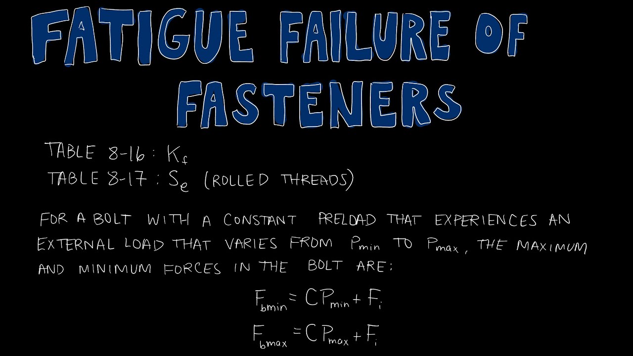
For a simplified concentric axial joint that remains closed and elastic, an idealized incremental bolt-load model is Fb = Fi + [Kb / (Kb + Kc)] × Fe. Here Fb is total bolt tension, Fi is initial preload, Kb is bolt stiffness, Kc is clamped-member stiffness, and Fe is external tensile load. Use consistent force and stiffness units. The equation does not apply after joint separation or when bending, eccentricity, plasticity, or other nonlinear effects dominate.
Maintaining preload can reduce the cyclic part of bolt tension while the joint stays in compression. If preload falls through embedment, settlement, thermal effects, loosening, or poor installation, the external load can produce a larger change in bolt force. The NASA manual details the load-sharing assumptions and illustrates how separation changes behavior. Validate the model against the real stack, contact areas, material properties, and load direction.
| Observed condition | Possible fatigue mechanism | Engineering check | Potential corrective action |
|---|---|---|---|
| Crack near first engaged thread | Thread-root stress concentration with fluctuating axial load | Check preload, thread engagement, load spectrum, material, and finish | Reduce alternating stress, improve joint stiffness, or select a validated fastener design |
| Fracture under the head | Bending, underhead stress concentration, or poor seating | Inspect bearing face, fillet, alignment, head support, and eccentricity | Correct seating geometry and load path; verify the specified head style |
| Loosened joint with fretting marks | Slip or separation increases cyclic motion and wear | Measure preload retention and joint slip under representative loading | Control preload and fit; use a validated locking or joint design |
| Corrosion pits near the fracture | Surface damage provides fatigue crack initiation sites | Review coating damage, environment, crevices, and cleaning | Correct material/finish pairing and protect the assembled joint |
| Different life across identical assemblies | Variation in friction, alignment, hole quality, or load sharing | Compare production lots, installation traces, and geometry | Improve process controls and test representative worst-case parts |
The table lists diagnostic possibilities, not a one-to-one failure code. Confirm the actual fracture surface and loading before changing a fastener specification.
Preload may be too low, too high, or too variable. Low preload permits joint slip or separation. Excessive preload can yield the fastener or damage the clamped material, leaving less margin for service load. Torque control is indirect because friction varies; the torque-tension relationship guide and screw torque chart guide explain why the installation condition must be validated.
Other contributors include cyclic transverse load, impact, vibration, bending, rotating parts, insufficient edge distance, poor hole fit, thread runout in a shear plane, corrosion, damaged threads, and temperature cycling. A longer grip can change bolt stiffness and load sharing. Use the bolt grip length guide when thread and smooth-shank position affect the joint design.
Corrective action should follow the diagnosed mechanism. A preload problem calls for reviewing the joint design and installation correlation; a bending problem calls for correcting alignment or eccentricity; corrosion fatigue calls for addressing the environment and surface protection. Replacing a broken bolt with an identical part may restore operation temporarily while leaving the cause untouched.
Property class or grade provides specified mechanical properties under its standard and test conditions. It does not by itself establish fatigue life for a particular geometry and load spectrum. The hex bolt grade guide summarizes mechanical designation differences. ISO 898-1 covers mechanical and physical properties for specified carbon and alloy steel bolts, screws, and studs. Its scope explicitly does not specify fatigue resistance. Consider the standard alongside joint analysis, surface condition, manufacturing process, and applicable product requirements.
NASA’s historical technical memorandum on mechanical fastening design also describes how preload and joint stiffness affect fatigue resistance. Because it is a general design reference, use current project codes and validated material data for any released design.
This engineering lecture introduces fatigue failure and cyclic loading. It supports the concepts above but does not calculate a service life for a specific fastener.

Define the service load spectrum, load direction, cycles, temperature, environment, and required life. Model the joint geometry and material stiffness, identify possible separation or slip, and calculate the bolt’s mean and alternating stresses using the governing method. Include bending and load distribution where present. If the load spectrum or boundary conditions are uncertain, use measurement or test fixtures on a representative assembly.
Validate the installation process and preload, then test the assembled joint with production parts and realistic cycles. Monitor loosening, clamp-load loss, fretting, cracks, and fastener failures. Use an inspection interval and rejection criteria suited to the consequence of failure. Do not set service life from an image, a static proof load, or a generic strength grade alone.
A fatigue test should represent the load ratio, mean load, frequency, environment, joint stiffness, surface condition, and assembly method expected in service. Accelerated tests can help compare designs, but increasing frequency or load may create a different heat, wear, or failure mechanism. Random or variable-amplitude service cycles may require a representative spectrum rather than a single constant-load test. Define the test fixture and termination criteria before collecting data.
Use multiple representative specimens and record failures as well as run-outs. A result from one fastener does not establish a reliable life distribution. Track lot, heat treatment, coating, thread process, installation preload, and fracture location. If the design changes after the test, identify which assumptions remain valid and repeat the affected portion of validation.
For fielded equipment, inspection can include visual examination, dimensional checks, dye penetrant or other nondestructive methods where the material and geometry allow them, and monitoring of preload or joint movement. These methods have detection limits. A crack at a covered thread root may not be visible without disassembly. Inspection frequency should follow consequence, accessibility, service loading, and approved maintenance data.
Preserve the failed fastener and fracture surfaces. Record the installation lot, fastener marking, material certificate, coating, lubricant, joint stack, tool trace, service cycles, temperature, vibration, and maintenance history. A laboratory fracture analysis can distinguish fatigue progression from overload, corrosion, embrittlement, or installation damage. Clean only as directed by the analyst because aggressive cleaning may destroy evidence.
Before changing the grade, identify the initiating cause. A stronger bolt may move failure to the internal thread or clamped component without correcting the load path. Correct confirmed preload loss, bending, fit, corrosion, surface defects, or process variation, then revalidate the entire assembly. TNHO’s hex and square-head bolt family illustrates relevant geometry; the approved drawing and test plan define the actual material, finish, dimensions, and application.
Yes. Repeated stress cycles can start and grow a crack even when the peak load stays below the one-time static tensile capacity. The load spectrum, preload, geometry, material, surface, and environment all matter.
No. Higher strength alone does not correct joint separation, bending, corrosion, poor preload, or a stress concentration. Evaluate the complete joint and use the material and fatigue design method required by the application.
In an aligned joint that remains clamped, preload and member stiffness can reduce the portion of external axial load that changes bolt tension. If preload falls and the joint separates, the bolt can experience larger cyclic stress.
Preserve and examine the fracture surface, thread roots, underhead transition, mating hole, bearing faces, coating, corrosion, and joint alignment. Review installation data, preload, cyclic loads, temperature, and service history before choosing corrective action.

 TNHO
TNHO