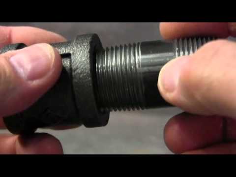
Cross-threading prevention starts by aligning the fastener axis with the internal thread and confirming the lead threads engage freely before applying powered torque. A screw that tilts, enters at the wrong angle, or meets an incompatible pitch can cut across the internal thread instead of following it. The joint may feel tight before the head seats, produce metal debris, strip the hole, or create false torque readings. Stop at unexpected resistance, back the screw out, inspect both parts, and correct the cause before continuing.
External and internal threads are helical forms that must engage with matching diameter, pitch, profile, and direction. At the start of assembly, the first thread turns guide the parts into alignment. If the screw is tilted or starts on the wrong thread, its crests can displace or shear material from the mating thread. The resulting path may spiral across the hole and prevent proper seating.
Cross-thread damage can reduce effective engagement and load capacity even when the screw appears tight. It can also leave chips in an electrical or mechanical assembly, damage coatings, jam a captive nut, or make future service unreliable. Do not treat tool torque as proof of correct assembly: a damaged thread can resist rotation before the bearing face reaches the joint.

Confirm the screw and hole are the correct size, pitch, thread direction, and part number. Check that the lead-in is clean and that the countersink, chamfer, or thread start is not burred. Hold the screw in line with the hole and start it using fingers or a low-force hand tool. For a conventional right-hand thread, gently turning backward until the lead thread drops into alignment can help identify the start; do not use this cue for left-hand threads or unusual thread forms unless the procedure specifies it.
Turn forward with light pressure. The first turns should advance smoothly and keep the fastener axis straight. If resistance rises immediately, the screw rocks, or it will not rotate freely before seating, stop. Back it out without force and inspect the male and female threads under good lighting. Do not use a power driver to overcome resistance.
Once the fastener has engaged correctly, use the approved driver and assembly method. A power tool should start only after alignment is established, with speed and torque limits selected for the screw and joint. Keep the bit fully engaged in the drive recess; cam-out can damage the head and make a thread problem harder to diagnose.
| Symptom | Possible cause | Immediate action | Follow-up check |
|---|---|---|---|
| Resistance on the first turns | Axis misalignment, wrong pitch, burr, or damaged lead | Stop and remove the screw gently | Compare thread diameter, pitch, direction, and start condition |
| Head does not seat but torque climbs | Cross-threading, bottoming, wrong length, or obstruction | Do not increase torque | Inspect engagement depth, hole depth, and stack thickness |
| Metal chips near the hole | Thread cutting across the mating form or debris in the hole | Remove loose debris using the approved cleaning method | Inspect both thread forms and control chip entry |
| Screw enters at an angle | Poor access, fixture movement, or off-axis tool | Reposition parts or use an alignment fixture | Check perpendicularity, location, and driver access |
| Fastener spins without clamping | Stripped internal thread or damaged captive nut | Remove from service and quarantine the assembly | Determine rework approval or replace the mating part |
| Repeated failures at one station | Wrong feeder part, worn bit, speed, or fixture shift | Pause the affected process | Audit feed, tool program, fixture, and operator method |
Do not attempt to solve a cross-threaded hole by forcing in a larger driver, using a longer screw, or adding threadlocker. Those changes can hide the damage without restoring the required thread engagement.
Specify compatible thread standards and classes. A metric screw and a visually similar inch thread can begin to engage and then bind; pitch and diameter must both match. Provide a suitable thread lead-in, edge break, or countersink for the part design, and avoid plating or coating buildup that takes the fit outside the specified limits.
Blind holes need enough usable full-form thread depth and clearance for the screw end, drill point, and any debris. The fastener length must allow the head to seat without bottoming. Thin sheet, soft alloys, plastics, and inserts require a mating thread designed for the expected installation and service loads.
NASA’s NASA-STD-5020 threaded fastening systems standard provides requirements for design, installation control, engagement, and preload in its stated spaceflight scope. The NASA Fastener Design Manual discusses thread forms, classes, dimensions, and selection. Use the applicable project standard for production parts rather than treating spaceflight guidance as a universal acceptance code.
Automated stations can reduce manual variation but can also turn a small misalignment into a stripped joint quickly. Control screw presentation, bit centering, axial force, starting speed, rundown speed, torque limits, and seating detection. Maintain bits and fixtures. Verify that a driver does not push the screw sideways as it enters the hole.
Use process monitoring to distinguish rundown torque from seating torque. A trace that rises too early, a sudden spike, excessive angle before seating, or a screw that reaches torque without reaching the expected depth should trigger a stop or review. Establish the accepted signature through pilot builds and correlate it to correctly assembled parts. Do not infer that a single torque threshold can detect every cross-thread condition.
Review the entire tolerance chain when the problem repeats in one station. A tapped hole near a bent flange, stacked plates with shifted holes, a countersink that is too shallow, coating thickness, burrs, a worn feeder rail, or an off-center bit can all push the screw away from its intended axis. Inspection should include the fixture and mating part, not only the fastener. When multiple screws clamp one cover, establish a sequence that locates the parts without drawing misaligned holes together under force.
For hand assembly, the operator should be able to feel the early engagement. If access prevents a straight start or the part is small, a pilot feature, guide sleeve, floating driver, or captive nut may reduce the chance of cross-threading. Evaluate such features for their effect on hole strength, service access, and required engagement. The aim is to make the correct start repeatable and visible before powered rundown begins.
This practical demonstration reinforces the importance of starting a threaded fastener straight and feeling for smooth engagement. Production processes still need their own approved tool settings and inspections.

If cross-threading is suspected, preserve the screw and mating component. Record the assembly station, tool, bit, torque trace, material, coating, lot, and observed symptom. Inspect the first engaged threads and hole with suitable lighting or magnification. Thread gauges can confirm some dimensional requirements but do not show every local tear or deformation. The FAA AC 43.13-1B contains general aircraft hardware maintenance practices; use the approved drawing and maintenance data for the specific aircraft or production assembly.
Repair only by an approved method and only if the finished thread meets the design requirement. Chasing a thread can remove material and is not automatically an acceptable repair. Replace damaged screws and mating parts when the load capacity, sealing, electrical connection, or service reliability is uncertain. Use the thread engagement guide, thread gauge inspection guide, and metric coarse versus fine thread guide for complementary design and inspection checks.
TNHO’s tamper-proof security screw family illustrates a countersunk four-hole drive design. The approved drawing should state thread standard and class, diameter, pitch, length datum, head and drive form, material, finish, mating-hole limits, thread depth, insertion direction, tool, and any automated process window. If assemblies are returned for repair, include an inspection and disposition method.
For procurement, identify mating nuts, inserts, tapped materials, coating condition, gauge requirements, sample approval, lot traceability, packaging, and any installation test. A screw’s appearance alone cannot confirm compatibility with the internal thread.
Common clues include early resistance, an angled screw, metal debris, a head that will not seat, or damaged first threads. Stop assembly and inspect both mating parts instead of increasing torque.
For many accessible machine-screw joints, a low-force hand start is a useful way to detect alignment problems before using a powered driver. Follow the product and process instructions, especially for inaccessible or automated joints.
No. Threadlocker does not restore thread form, correct pitch mismatch, or provide reliable engagement in a damaged hole. Resolve the mechanical damage using an approved repair or replacement process.
Inspect the male thread and drive recess. Replace the screw if its thread, coating, or head is damaged, and separately assess the mating hole. Reuse only when the approved specification permits it.

 TNHO
TNHO