Hex socket set screws for meter internal assemblies are headless fasteners driven through an internal hex recess, but the drive alone does not define the right joint. Select the point geometry, mating feature, and tool-access arrangement from the controlled assembly drawing before matching a product.
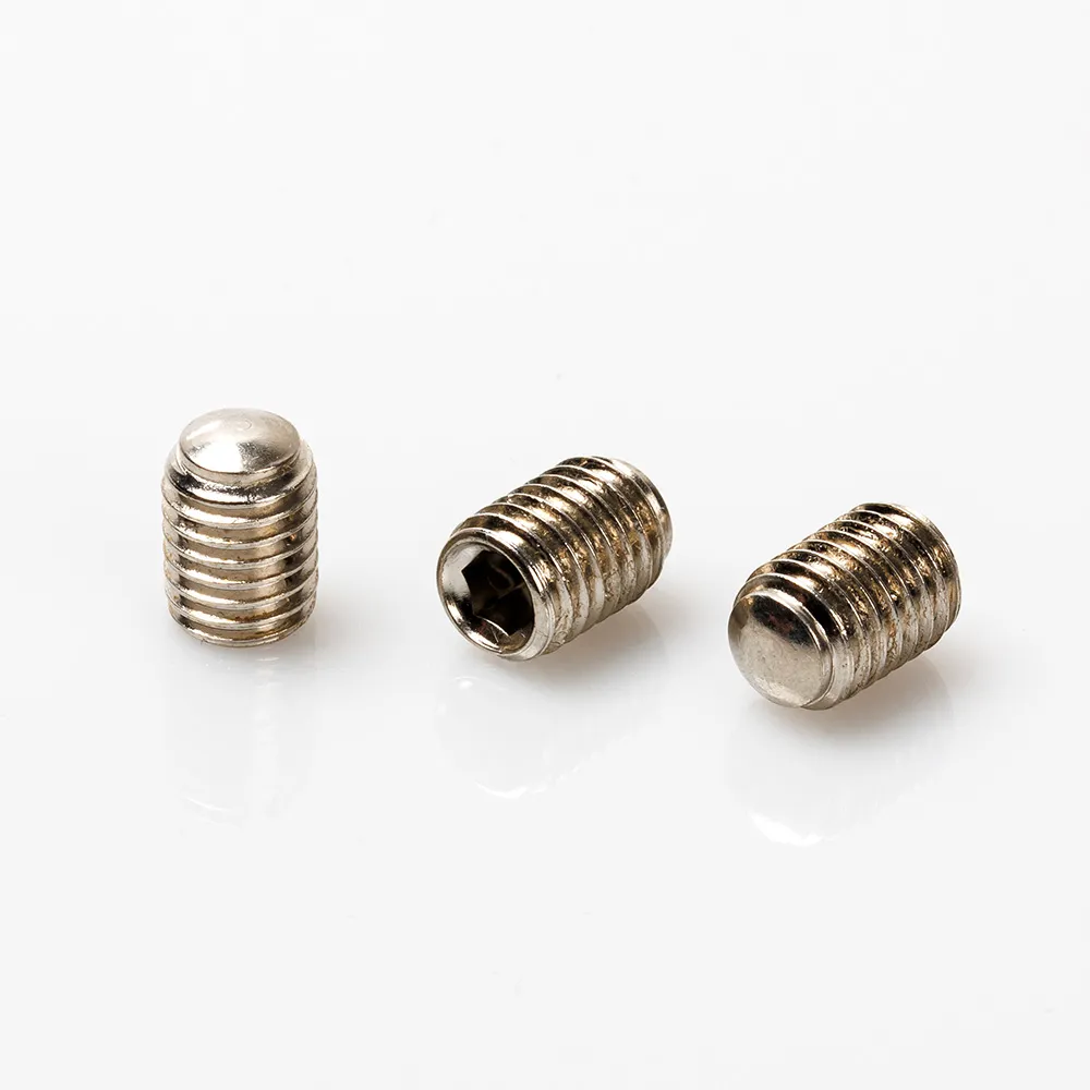
A hex socket set screw has no projecting external head and is driven through a recessed hexagonal socket. This form can be useful inside a meter assembly where surrounding components limit external-head clearance, provided the correct key can reach and engage the recess at the approved assembly stage.
The term “hex socket” describes the drive. It does not select the point, establish a retention capacity, or confirm that a screw is compatible with a particular internal component. The buyer still needs a defined thread, a specified contact feature, and a clear statement of what the screw is meant to locate or retain.
Ames Web’s dimensional reference maps the common flat, cone, dog, and cup point forms to the ISO 4026–4029 family. That mapping is helpful for terminology, while the released drawing remains the source for the part actually required.
Start from the mating feature, not from a generic claim that one point is best. The contact surface may be a prepared flat, a locating hole, a groove, or another controlled feature; each asks a different question about alignment, surface marking, and service.
| Point geometry | Interface question to resolve | Selection boundary |
|---|---|---|
| Flat point | Does the interface need broad contact with limited penetration? | Confirm the surface and the intended positioning function. |
| Cup point | Is localized contact acceptable on the specified mating area? | Do not infer a retention result without the joint design. |
| Cone point | Is the drawing calling for a concentrated locating contact? | Review the prepared feature and service implications. |
| Dog point | Is a dedicated hole or groove intended to control location? | Match the point to the defined feature rather than a smooth surface. |
This is why point style belongs in the drawing or specification. Accu’s guide describes how point shapes trade contact, alignment, and potential marking; the article does not turn those general descriptions into a meter-model performance claim.
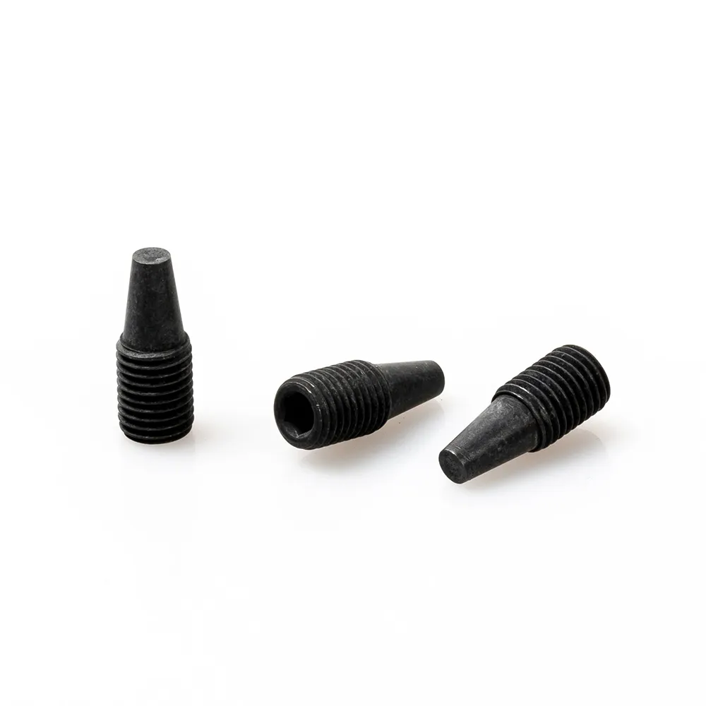
Inside a meter assembly, the key must enter the socket along the intended tool path. Check assembly tool access and whether adjacent boards, terminals, walls, or covers obstruct that path before an assembly sequence is frozen.
Recess engagement also needs a controlled work instruction. Confirm the tool type, the available approach clearance, and whether the operator can keep the key seated through the required operation. These checks are about access and repeatability; they do not justify an exact tightening value without approved product and joint data.
Consider the service sequence as well:
The answers make the specification more useful to both the assembly team and the supplier. They also prevent a recessed drive from being selected on appearance alone.
An internal rotating or locating component needs a defined shaft or mating interface. A smooth shaft, a flat, and a locating hole are not interchangeable descriptions because they give the point different surfaces and different location control.
Engineering forum questions about D-cut shafts commonly ask whether torque is carried by the screw or distributed through the mating shape. The useful takeaway is not a universal calculation; it is that the drawing should show the shaft form and the intended load path before a set-screw callout is finalized.
Review these interface details together:
If the required component has no controlled mating feature, record that as a drawing callout question rather than silently choosing a point type. This keeps the internal-assembly discussion connected to evidence instead of a generic fastener preference.
The RFQ should give a reviewer enough information to compare the requested screw form with the actual internal assembly. It should not rely on a photograph or assume that a generic size name defines the full contact condition.
| Buyer should provide | Decision effect | Common omission |
|---|---|---|
| Current drawing revision and thread callout | Identifies the controlled interface | An old drawing or a verbal thread description |
| Point geometry and mating-feature detail | Connects the point to a real flat, hole, groove, or surface | Naming a point with no shaft detail |
| Required length and internal clearance envelope | Supports an interference review | Showing only the outside of the enclosure |
| Tool-access envelope and assembly stage | Tests whether the hex key can engage the recess | Checking access only before nearby parts are fitted |
| Function and service requirement | Separates locating, adjustment, and retention needs | Calling the joint “secure” without a stated function |
First, confirm the mating feature and the thread. Next, review point geometry and the full internal clearance envelope. Finally, verify the tool path and service sequence; this is more reliable than choosing a product first and attempting to fit it into the mechanism later.
For broader context, the site’s Electric Meter Fastener Guides and set screw basics provide related reading without replacing the released assembly drawing.
Hex socket set screws fit a compact, documented internal interface when the specified point, thread, and tool path are compatible. They are less suitable as an assumption when the load path is undefined, a smooth surface cannot accept the proposed contact, or a different retention approach is required by the assembly design.
The scope of standards matters here. ISO 4026 covers flat-point hexagon socket set screws, and ISO 4029 covers cup-point hexagon socket set screws; both state that the products they cover are not intended for tensile load. That statement applies to the scope of those named standards, not automatically to every component or every meter assembly.
Important: Do not use a standard designation as evidence of a product approval, a material grade, or a finished-joint result. Confirm the applicable drawing, product documentation, and functional requirement together. (ISO 4026 scope)
When movement has a high consequence, the required interface is uncertain, or the component must transmit an undefined load, request a joint-level engineering review. A product family label cannot resolve those unanswered design inputs.
Once the drawing confirms an internal hex drive, the correct point, and the mating feature, start by reviewing the site’s electric meter screw range. This keeps the selection attached to the relevant product line while preserving the difference between a category page and a controlled specification.
For an approved drawing that specifically calls for the form, review the hex socket set screw product details. Compare the controlled requirement with the product information instead of assuming that a slotted, sealing, or security screw is functionally equivalent.
To begin a documented review, send the internal-assembly drawing with the thread/point callout, mating-feature description, tool-access envelope, and service expectation. The site’s industrial fastener categories are also available when the bill of materials is still being organized.
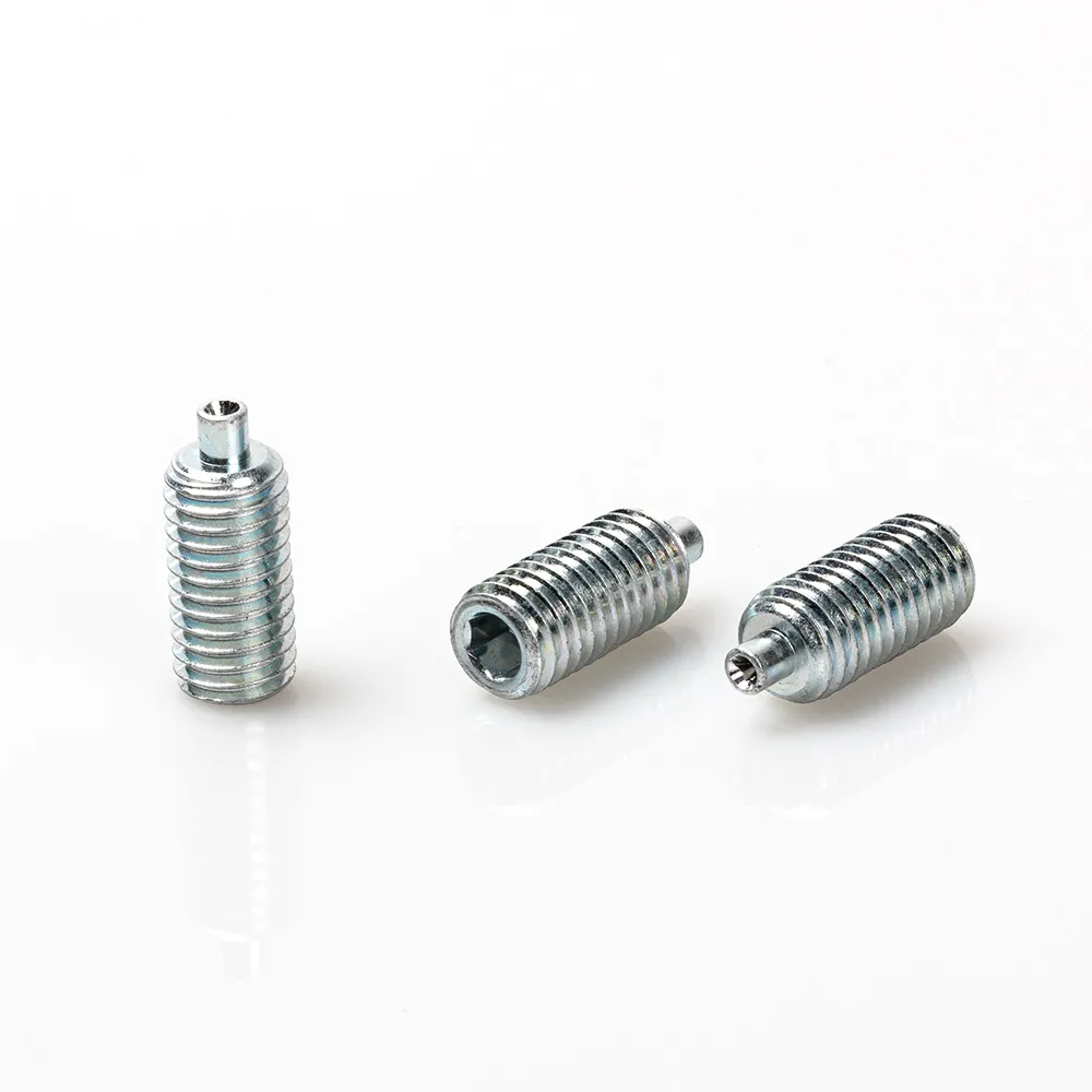
A hex socket set screw is a headless threaded fastener with an internal hex recess for the installation tool. It is used to position or retain a component through a defined contact interface.
Use the point style that matches the documented mating feature and function. Confirm whether the point meets a flat, locating hole, groove, or other controlled surface.
No. The recess controls the installation interface, while the thread, point, mating feature, and joint function still need to be specified.
It can be contacted by a set screw, but the design should determine whether marking is acceptable and whether a flat or other prepared feature is needed for controlled location.
Include the thread callout, point geometry, mating-feature detail, required length, clearance envelope, tool access, and the joint’s functional and service requirements.
No. The ISO pages state that the hexagon-socket products covered by those documents are not intended for tensile load.
Review another method when the load path is unclear, the mating interface is not controlled, the surface cannot accept the point contact, or the consequence of movement calls for separate engineering validation.

 TNHO
TNHO 


