Slotted set screws for electric meter shafts should be selected from the confirmed shaft interface, thread callout, and assembly-tool access—not from the drive slot alone. A slotted drive can suit a compact serviceable assembly when the approved blade can engage it, but point geometry and the mating feature still determine how the component is located.
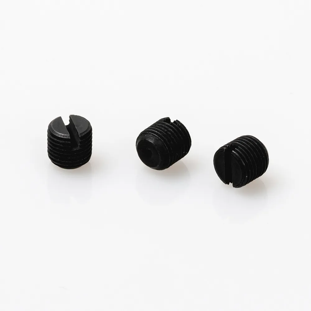
A set screw retains or positions one component against another without an external head projecting beyond the assembly. That compact arrangement is useful when a meter mechanism has limited radial clearance, yet the drawing must still identify the thread, point, and mating feature rather than merely saying “set screw.”
For this application, keep two decisions separate. The slot decides how the screw is driven; the point and shaft feature decide how contact is made. Machine Design’s set-screw guide treats drive type and point style as separate selection variables, which is a useful starting point for a meter shaft review.
The intended function should also be stated plainly. Is the screw locating a collar, limiting axial movement, holding an adjustment setting, or retaining a component during assembly? A concise functional statement prevents a buyer from substituting a visually similar screw whose contact geometry does not suit the interface.
Unlike a recessed hex drive, a slotted drive needs a blade to stay aligned with its slot while the operator turns it. Review drive access, the available approach path, the surrounding wall or component clearance, and whether the work instruction calls for service access after the meter is assembled.
The slot can be practical where the approved tool is a flat blade and the operation is accessible. It is not a shorthand for a retention level, a security feature, or a material requirement. Those conclusions need a drawing, a validated joint design, and the applicable product documentation.
Use the actual assembly envelope to answer three questions:
These questions are more useful than assuming that one drive type is always better. A forum question about attaching something to a smooth shaft highlights the same practical concern: the interface and service condition matter as much as the fastener itself.
Point geometry determines the nature of contact with the shaft or mating component. Accu’s technical guide distinguishes point styles by their contact and alignment roles; use that general logic only after the actual interface is known.
| Confirmed interface condition | Selection question | Practical direction |
|---|---|---|
| A prepared flat or broad contact area | Must the contact avoid a concentrated mark? | Review a point that distributes contact rather than assuming penetration is desirable. |
| A locating hole or groove | Is repeatable location the main function? | Review a point geometry intended to engage the defined feature. |
| A smooth round shaft | Is marking acceptable, and how is location controlled? | Do not treat friction alone as a complete design description; review the shaft preparation and functional load path. |
| A component that will be adjusted or removed | Must the interface remain serviceable after contact? | Document the expected contact effect and the removal/service method. |
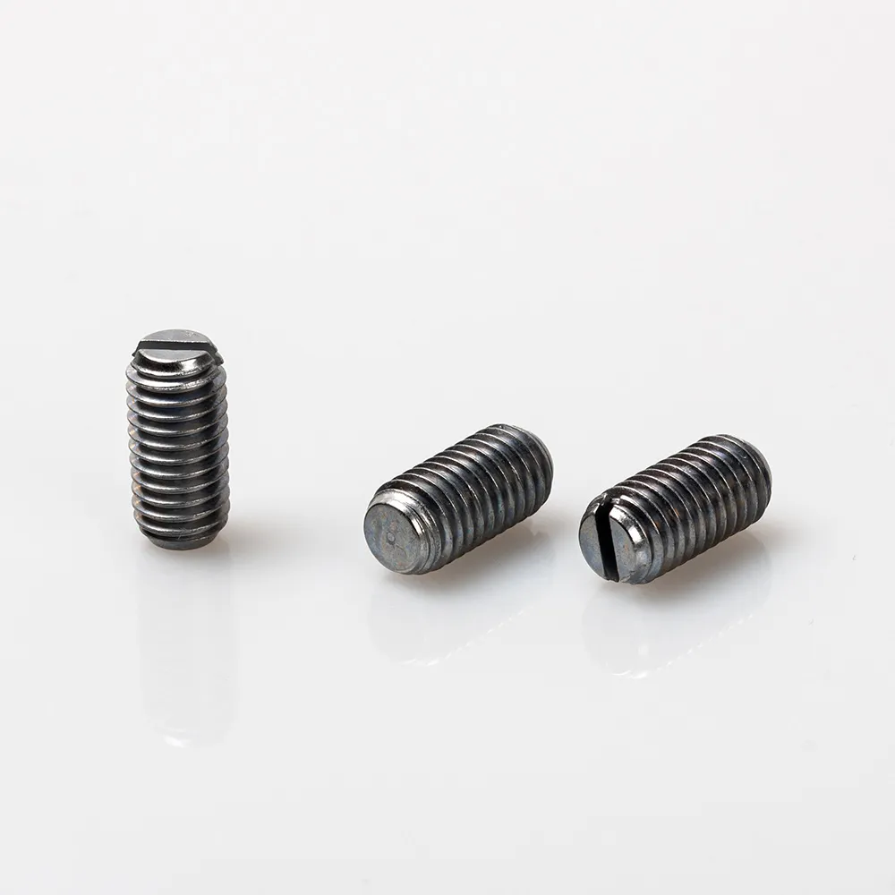
The first useful question is not “which point is strongest?” It is “what feature is the point intended to meet?” A point selected for a prepared locating feature should not be swapped casually into an interface that needs repeatable adjustment or a protected surface.
When a shaft is smooth, the design team should decide whether a shaft flat or locating feature is required before releasing the fastener callout. Engineering discussions about D-shaped shafts repeatedly show why this distinction matters: a prepared feature gives the screw a defined contact location instead of leaving the result to an undocumented surface condition.
Review the mating side as carefully as the shaft. Confirm the threaded hole location, available engagement depth, assembly clearance, nearby wall thickness, component stack-up, and whether the screw end could interfere with another internal part. These are component drawing review items, not values that can be inferred from a product photograph.
Important: A set screw is not automatically a substitute for every retention method. ISO 4026 and ISO 4029 state that the hexagon-socket products covered by those documents are not intended for tensile load. Those documents do not specify slotted parts; they illustrate why the intended load and applicable specification must be checked instead of assumed.
If the assembly has a high consequence of movement, uncertain loading, or no controlled shaft feature, pause the selection and obtain a joint-level engineering review. That is a design boundary, not a claim about any particular product.
A usable RFQ starts with the drawing and the function of the contact. It should enable the supplier and buyer to compare the requested feature with the approved assembly, without asking either party to guess torque, material, or compliance requirements.
| Buyer should provide | Why it matters | Common omission |
|---|---|---|
| Thread designation and drawing revision | Identifies the tapped interface and controlled revision | Sending a photo without the current callout |
| Shaft or mating-feature detail | Connects point geometry to an actual contact surface | Naming a point but omitting the flat, hole, or groove |
| Required screw length and interference envelope | Allows a clearance review in the internal assembly | Measuring only the visible portion of the component |
| Tool-access description | Confirms the slot can be engaged in the intended sequence | Assuming a screwdriver can reach after adjacent parts are installed |
| Functional and service requirement | Clarifies whether the joint locates, adjusts, or retains a part | Calling every requirement “locking” without context |
Provide the assembly stage at which the screw is installed and, if relevant, the stage at which it is removed. This gives the reviewer a concrete basis for checking access and serviceability without converting a generic fastener rule into an unsupported product specification or performance promise.
For related orientation, the site’s Electric Meter Fastener Guides and meter screw specification guide can help a buyer organize the broader fastener context.
Choose a different path when the drawing needs a different drive, the shaft interface is not defined, or the joint’s function cannot be described as local positioning or retention. A slotted drive should not be selected simply because it looks compact; assembly access and the approved work method have to support it.
The fit boundary is especially important where an internal component carries an unclear load path, where a smooth surface must remain unmarked, or where repeated servicing changes the contact condition. In those cases, the fastener type and retention method require a documented engineering decision.
Nor should an ISO designation be copied into a slotted-screw callout without checking scope. ISO 4026 and ISO 4029 are useful references for named hexagon-socket forms, not blanket evidence that every set screw shares the same dimensions or intended use.
After the drawing confirms that a slotted drive, selected point, and shaft interface belong together, review the electric meter screw range before narrowing the product discussion. That route keeps the article connected to the relevant product line without treating a category label as a verified specification.
For a project whose controlled drawing calls for a slotted set screw, begin with the site’s slotted set screw product details. Use the product review to compare the drawing’s required drive and point with the available product information; do not substitute a hex-socket part merely because both are headless set screws.
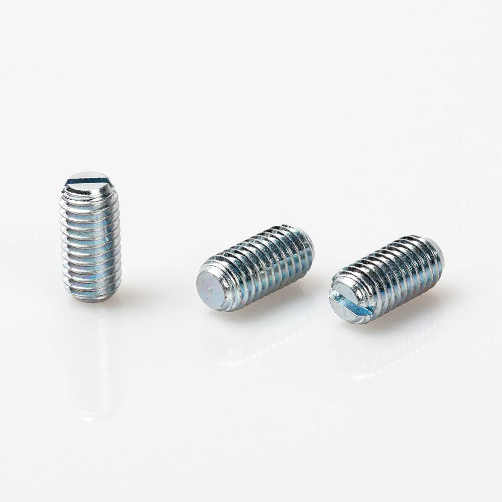
The next step is to share the shaft drawing and assembly details: the thread callout, mating feature, access envelope, installation stage, and service expectation. Buyers who are still defining the broader bill of materials can also review the site’s industrial fastener categories.
A slotted set screw is a threaded, headless fastener with a straight driver slot. It is used to position or retain a component through direct contact with a shaft or mating feature.
No. The drive affects how the screw is installed, while the actual interface, point geometry, thread, and joint design must be reviewed for the intended function.
Select the point only after confirming whether it meets a flat, locating feature, smooth surface, or another defined interface. The drawing should describe that contact relationship.
It can contact a smooth shaft, but the team should determine whether marking is acceptable and whether a prepared feature is needed for controlled location or serviceability.
Provide the current drawing revision, thread callout, point requirement, shaft or mating-feature detail, clearance envelope, and installation/service context.
Do not assume so. ISO 4026 and ISO 4029 say the covered hexagon-socket products are not intended for tensile load; confirm the applicable specification for the part being considered.
Evaluate another method when the load path is unclear, the interface is not controlled, the surface cannot accept the intended contact, or the consequence of movement needs a separate joint-level review.

 TNHO
TNHO 


