Press fit threaded inserts add a reusable metal thread by being pressed into a prepared hole without a separate heating operation. Their success depends on the insert’s retention profile, the host material, the actual hole dimensions and a controlled installation stroke. A brass insert that looks suitable in a photograph is not automatically approved for cold insertion into your plastic boss. Start with a part-specific installation drawing and confirm retention in representative molded parts before releasing production. This guide focuses on cold insertion, hole control and acceptance evidence for OEM assemblies; it does not replace the approved instructions for a particular insert.
A press-in insert enters a hole under an axial load. The outside profile engages the surrounding material and the internal thread subsequently accepts the assembly screw. That sequence differs from molding plastic around an insert or deliberately softening a thermoplastic around a heated insert. Substituting one process for another can change both the stress left in the boss and the resistance to rotation.
Use the general threaded-insert guide to identify the available families, then specify the intended installation method on the drawing. Do not treat every knurled brass component as a universal press-fit part. Straight knurls, opposing knurls, undercuts and lead-in shapes have different purposes. Ask whether the exact part number is intended for cold insertion into the exact resin grade and manufacturing process. A drawing, application recommendation and successful trial are stronger evidence than an online description that simply says “for plastic.”
The host is part of the fastening system. Specify its resin grade, reinforcement, molding process and conditioning state, rather than writing only “plastic.” A stiff, brittle boss and a more ductile boss can respond differently to the same inserted profile. Printed prototypes may also have layer boundaries and voids that are absent from production moldings. Their installation results should not automatically release a molded design, or vice versa.
Material behavior changes with temperature, time and environment. NIST's polymer-property compilation is useful background for why a polymer designation and test conditions matter; it supplies no universal interference value for this assembly. Obtain current grade-specific information from the resin producer and validate the actual joint. Include expected cleaning agents and moisture exposure where relevant. A successful room-temperature installation does not demonstrate retained strength after a sustained service load or repeated hot and cold operation.

Call out the prepared hole diameter, depth, entry detail and the reference surface for final installed position. For a molded hole, examine taper and roundness along the engagement length. A measurement at the entrance alone can miss a narrower section deeper inside. For a machined hole, distinguish the cutting-tool size from the measured result in the finished component. Burrs and an uncontrolled lead-in can affect alignment and installation force.
Use the insert supplier's approved hole recommendation as a starting point for trials, not a transferable rule for all products. Document which outside feature is used to determine interference. A knurled crest and a smooth waist are not interchangeable measurement locations. When a blind insert is used, separately verify insert seating clearance and screw-tip clearance. The insert may seat correctly while the chosen screw later bottoms out and creates misleading tightening resistance.
The table below is a practical trial-planning checklist. It contains no invented temperature, diameter or retention limit. Every acceptance value belongs in the approved component drawing and validation plan. Use these decisions to identify what evidence is missing before ordering a production quantity.
A useful comparison includes the host as well as the insert. Keeping the metal part constant while changing resin, boss dimensions or hole preparation can still create a different fastening system. Record those changes explicitly. If a sample is accepted only because an operator uses extra force to finish the stroke, the process has not yet demonstrated a repeatable operating window. Compare installation observations with the retention result from the same identified sample, and avoid combining unrelated measurements into one apparent pass.
| Review item | Decision input | Required action |
|---|---|---|
| Host condition | Exact grade and conditioning | Test production-representative bosses |
| Hole geometry | Measured diameter, taper and depth | Inspect the engagement region, not just the entrance |
| Insertion setup | Tool nose, support and stroke | Check position, tilt and force observations |
| Installed retention | Axial and rotational requirements | Use separate documented test methods |
| Service duty | Exposure and repeated assembly | Repeat relevant checks after conditioning |
This qualitative checklist is an engineering planning aid; exact acceptance values require the approved part, host and procedure.
A controlled press and an appropriate installation nose make the loading path easier to reproduce. The tool should bear on the approved insert surface without damaging the thread or driving debris into it. The fixture should support the surrounding component so that the installation stroke does not simply bend the cover, tilt the boss or transmit load through a fragile neighboring feature. Confirm access with the complete assembly, including ribs and cable-routing features.
Before a trial, verify insert orientation, part seating and tool alignment. Use the approved stroke or installed-position control, and observe force where the equipment permits it. Do not publish a universal press force for a family described only by thread size. Hole geometry, material and insert profile all affect the outcome. Stop and investigate an unusual force trace, a visible crack or a tilted insert; forcing the next cycle through the same problem creates scrap rather than qualification.
Incoming inspection should identify the correct thread, outside retention profile, length and entry orientation. Use suitable equipment for each feature. A caliper is useful for accessible external dimensions, but an internal thread generally requires the specified thread inspection method. Measuring across a rough knurled surface also needs a defined convention so that different operators do not record different features under the same dimension name.
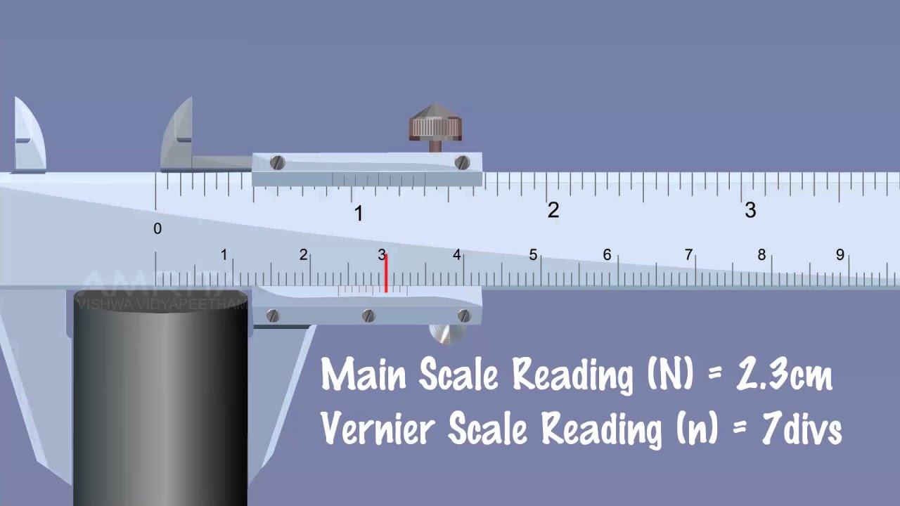
The educational caliper video below explains instrument reading and handling. It is relevant to the measurement stage, not a demonstration of this insert's approved installation procedure. Keep instrument calibration and sample identification in the inspection record. After insertion, inspect final position, tilt, boss damage and thread usability. A screw that can be turned into the insert proves neither axial retention nor resistance to rotation. Treat dimensional inspection and installed-joint performance as separate checks with separate acceptance criteria.

A retention trial should reproduce the failure modes that matter to the product. Axial extraction and rotation resistance are distinct measurements. A part can resist being pulled out yet rotate during assembly, or remain rotationally stable while the host cracks under axial loading. Define the fixture, load direction, displacement or rotation measurement and failure description before testing. Do not compare results from differently supported samples as though they were interchangeable.
For service exposure, consider sustained loading, repeated screw removal and relevant temperature or moisture conditioning. Select the sequence from the product's actual requirements. Record whether failure occurs in the metal thread, the retention interface or the host boss. The linked pull-out testing guide discusses axial-test planning in more detail. General bolted-joint principles in NASA's Fastener Design Manual help explain the later screw load path, but its values should not be transferred into an unqualified plastic-insert design.
A cracked boss can indicate excessive interference, insufficient surrounding material, unsuitable resin condition, poor support or misalignment. A loose insert can indicate an oversized hole, an incorrect retention profile or damage during installation. A tilted insert points toward entry alignment, tool contact or fixture control. Diagnose the actual observations rather than immediately increasing insertion force or changing to a larger part.
Keep failed samples and photograph the section or damaged region where practical. Compare actual hole measurements with the specified limits and check the press record for the same cycle. If rotation appears only during screw tightening, investigate screw engagement, bottoming and the torque procedure as well as insert retention. Unapproved adhesive or heat can conceal a problem while creating a new process. Any change to the approved method should go through a documented engineering trial and repeat the relevant acceptance checks.
An effective RFQ includes the internal thread designation, insert envelope, retention geometry, host material, boss drawing, prepared-hole limits, installed position and screw arrangement. Add expected service exposure and the required rotation and axial-retention evidence. Identify whether the buyer supplies production bosses for trials and whether results must include installation-force observations. Agree how changes to tooling, resin grade, insert finish and supplier lot are handled.
TNHO's knurled-insert product gallery provides a real geometry reference for discussing a custom component. The illustrations here preserve the listed straight-knurled profile; they do not establish its approval for your cold-insertion application. Request that approval against the actual drawing. Compare heat-set and ultrasonic routes only when cold insertion cannot meet the requirement, rather than blending their settings into one instruction. Release the combination of part, hole, material, fixture and procedure that was validated, and retain the test evidence with the purchasing specification.
MeitY OLabs educational demonstration by amritacreate. It supports external dimensional inspection; it is not an insert-installation tutorial.
Discuss the actual component using TNHO’s relevant product gallery. Continue with threaded-insert families, axial pull-out testing, heat-set installation, ultrasonic installation.
The guidance above combines general manufacturing principles with a proposed part-specific review process. The sources provide background, not approval or numeric limits for a TNHO component. Use NIST polymer-property compilation, NASA Fastener Design Manual alongside the current component drawing and validated procedure.
No. Similar appearance does not establish the approved installation process. Confirm the exact retention profile, hole requirements and host material, then test production-representative parts.
Use the approved recommendation for the exact insert and host as the trial starting point. Specify how the finished hole is measured and qualify the permitted tolerance range; thread size alone does not determine the hole.
Installation force is a process observation. It can help detect variation, but it does not independently establish extraction resistance, rotation resistance or service life.
Only if it represents the relevant production material, geometry and process, and the agreed acceptance checks are satisfied. Otherwise use it to identify issues and repeat qualification on production-representative parts.

 TNHO
TNHO