Heat set inserts for plastic create a reusable metal thread by installing a suitable insert into a compatible thermoplastic boss with a controlled heating and pressing process. Successful installation depends on the specific insert, resin, hole geometry, support, temperature history and cooling procedure. There is no universal hole diameter or soldering-iron setting for every insert. For OEM production, start with the insert supplier’s validated geometry and the resin manufacturer’s processing guidance, then qualify the actual assembly. This guide focuses on heat installation, boss design, pilot holes and acceptance evidence rather than assuming any knurled brass part is automatically heat-set qualified.
Identify the exact resin grade, filler content and manufacturing process before choosing the insert. Thermoplastics can soften with heat and solidify again; cured thermosets do not offer the same remelting behavior. TWI’s thermoplastic and thermoset comparison explains that basic material distinction. It does not supply an installation setting for a particular resin or boss.
Request an insert design explicitly intended for the selected installation process. A knurled outside surface alone does not prove suitability. TNHO’s precision knurled insert range supplies the real product geometry used in the illustrations here; the pictures demonstrate shape, not an approved heat-installation rating. Confirm the part drawing and process compatibility with the supplier. If the material or insert cannot support the intended process, select a different fastening approach before changing the production hole.
The internal thread size does not determine the required plastic hole diameter by itself. The outside knurls, taper, lead-in, length and displaced-material volume all matter. Obtain the hole recommendation for the exact insert and establish its tolerance for your resin and manufacturing process. The finished hole should be measured in production-intent parts rather than assumed to match the CAD model.
Distinguish a printed hole from a molded hole. Printing orientation, local solid material, shrinkage and post-processing can change the geometry around the boss. A molding process introduces its own material and tooling variation. Document whether the hole is formed directly, drilled later or finished by another operation. Check depth and the entry condition as well as diameter. A successful insertion in one prototype is useful evidence, but it is not a tolerance study. Include the selected hole geometry in the controlled drawing and preserve the link to the insert revision.

The boss must provide sufficient surrounding material for the chosen insert and the actual service load. Avoid prescribing one universal wall thickness or boss-to-insert ratio without a validated design basis. Review the available envelope, nearby ribs, edge distance, recesses and the path by which the installed screw transfers load into the part.
Include the screw and attached component in the design review. The insert may survive installation but the surrounding plastic can still crack, distort or creep during tightening and service. Check whether the screw bottoms in a blind hole or presses against the supporting structure. Provide clearance for the screw’s usable thread and any approved assembly tolerance. A thin enclosure wall should not become the unintended load stop. Define what remains supported while the insert is hot and what carries the final clamp force after cooling. These questions turn a generic insert selection into a review of a complete fastening feature.
For production, control the heating source, insert contact, axial alignment, insertion movement and final position. A displayed tool temperature is only one process variable; it does not establish the temperature history of the insert or surrounding plastic. Record the equipment, tip geometry, part support and timing used for the approved trial.
Start from supplier guidance and resin limits, then develop an acceptable process window using representative parts. Observe insertion behavior and inspect the cooled result. A setting that produces a neat surface can still leave insufficient material engagement below it. Conversely, forcing the insert quickly into a barely softened boss can damage the surrounding feature. Agree which variables operators may adjust and which require engineering approval. The checklist below is intended to define evidence and acceptance actions, not prescribe universal temperatures. Numerical settings belong in the qualified work instruction for the actual insert, polymer and equipment combination.
| Decision | Information to request | Acceptance action |
|---|---|---|
| Material compatibility | Resin grade and intended heat-installation insert | Reject unsuitable process combinations |
| Pilot hole | Diameter, depth, entry and manufacturing variation | Validate production-intent tolerances |
| Installation control | Tooling, support, motion and thermal history | Release a measured process window |
| Cooled assembly | Installed position, thread access and retention | Verify the complete load path |
This is a purchasing decision checklist, not a table of universal material or coating limits. Use the approved drawing and applicable standard for numerical acceptance.
Locate the component in a fixture that supports the boss without distorting nearby walls. Align the insert and installation tool with the intended thread axis. The fixture should allow loading and unloading while protecting cosmetic surfaces and any delicate features. Verify that the tool contacts the insert as intended and does not damage the internal thread.
Define the final installed position relative to a stable datum: flush, recessed or protruding as required by the design. Avoid letting the operator judge depth from an irregular printed surface. Inspect squareness and whether material has flowed into the bore or onto a bearing surface. Provide an approved cooling and release sequence so the insert is not disturbed before the local polymer can support it. For automation, check repeatability across all fixture positions, not only the easiest cavity. If the tool becomes contaminated with resin, define how it is cleaned and how the first part after cleaning is checked.
Measure the installed height, alignment and thread access after the part has cooled according to the approved process. Inspect for cracks, displaced material, voids and damage to the boss. A screw turning freely into the insert is a useful check of access and thread condition, but it cannot establish pull-out resistance or torque-out performance.
Define tests that represent the actual load directions and attachment stack. Our thread insert pull-out test guide covers the evidence needed for an axial retention assessment. Also evaluate rotation where that is relevant. Record whether failure occurs in the plastic, at the insert interface, in the screw or in the fixture. Do not publish a generic force rating from another resin or geometry. If a supplier provides data, confirm the specimen, installation method and test conditions before applying it to your component.

The heating operation establishes the insert in the boss; later screw tightening establishes the attachment’s clamp condition. These are separate processes with separate acceptance criteria. Set the tightening method for the complete assembly rather than borrowing a metal-joint torque table. The plastic bearing surface and the installed insert both need to support the intended action.
Check screw length, usable engagement and bottom clearance across the tolerance range. A bottomed screw can create a misleading tightening response before the attached part is properly clamped. Repeated assembly can also change the surrounding plastic even when the metal thread remains usable. Define the maintenance cycle and verify representative disassembly and reassembly. Review our broader threaded insert overview for alternative attachment methods, and thread-forming screws for plastic when comparing an insert system with direct fastening into the polymer.
Heat installation transfers thermal energy through the selected heating arrangement. Ultrasonic installation uses vibration and a compatible tooling system to generate local heating. The same internal thread designation does not make two insert designs interchangeable between those processes. Ask the supplier to confirm process suitability and validate any proposed change on the actual molded or printed feature.
TWI’s ultrasonic joining explanation provides background on vibration-based joining. It is not a heat-set insert design chart. Use the separate ultrasonic insert process guide for horn, fixture and vibration-control questions. In an equipment comparison, measure total handling, insertion, cooling, inspection and rework time under the approved conditions. Do not select a process from an unsupported claim that one method is always faster or stronger. Compare demonstrated results against the same acceptance requirements.
Use trials that cover realistic insert lots, resin variation, part geometry and equipment conditions. Include the worst permitted hole and boss dimensions, together with representative support and installation access. Define how many specimens and which combinations are needed from the application risk and agreed validation plan. Keep the test evidence traceable to the exact revisions.
For printed parts, include the specified orientation and local build settings. For molded parts, examine relevant cavities and process variation. Conditioning and service exposure may affect acceptance, so define them before testing rather than after a weak result appears. Record both acceptable settings and rejected conditions to avoid rediscovering known failures during production. Release the process only when the approved window produces compliant parts consistently. If a resin, insert supplier, knurl geometry or fixture changes, decide which checks must be repeated before returning to normal production.
Send the insert and component drawings, internal thread requirements, polymer grade, manufacturing method, hole dimensions, boss envelope and installation approach. State the required quantities, delivery condition, lot identification and any first-article evidence. Include installed-position limits and the functional loads the completed fastening feature must withstand.
Ask the supplier to identify process assumptions and proposed changes explicitly. Do not accept a quote described only as brass insert M4 when outside geometry and installation compatibility are essential. Agree responsibility for the hole recommendation, tooling development, retention testing and final application approval. Packaging should preserve the insert geometry and prevent contamination relevant to installation. Keep the approved sample, drawing and installation record together. This helps purchasing compare equivalent offers and gives production a clear boundary for substitutions, rather than leaving the operator to compensate for an unreviewed insert with a hotter tool or greater pressing force.
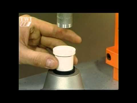
TWI’s research and training video explains ultrasonic plastic joining, the alternative process discussed above. It helps distinguish vibration-generated local heating from conductive heat installation. It does not demonstrate heat-set insert installation, qualify the illustrated TNHO insert or prescribe a pilot hole or temperature.
No. Confirm that the specific insert design and polymer are suitable, then validate the actual hole, boss and installation process.
Use the part-specific supplier recommendation and qualify the tolerance in your resin and manufacturing process. Internal thread size alone is insufficient.
There is no universal setting. Establish the process from the insert, resin, tool contact, timing and approved validation evidence.
Yes. Appearance cannot independently establish material engagement or retention. Inspect cooled parts and test the relevant functional loads.

 TNHO
TNHO 


