A thread insert pull-out test measures the response of an installed insert and its surrounding material when a specified axial load attempts to remove the insert. The result belongs to the complete tested system: insert geometry, substrate, hole, installation process, conditioning and fixture. It is not an intrinsic strength rating of the insert alone. OEM buyers should define the intended failure criterion, loading method and acceptance requirement before testing. Record the force–displacement response and failure mode, then connect every specimen to its manufacturing and installation history. A single maximum-force value cannot establish a safe service load for every application.
Identify the insert type and the way it is retained in the host material. Knurled, molded-in, heat-installed, press-fit and mechanically anchored inserts can rely on different interfaces. Do not assume a test procedure for one retention mechanism represents another. The substrate and installation method should match the approved application, including any supplier-specific dimensional requirements.
Describe what the assembly must do. The service load may include tension, bending, vibration, temperature changes or repeated fastening. An axial pull-out test addresses a defined loading condition, but it does not automatically cover torsional resistance, repeated screw installation or long-term creep. Select complementary checks when the application needs them.
Also distinguish extraction from other failures. The internal thread might strip, the test screw might fracture, the host coupon might break, or the fixture might slip before the insert is removed. Those events provide different information. Specify whether the test is intended to measure extraction resistance, system failure load, displacement at a stated load, or another property.
The coupon must represent the actual host material and geometry sufficiently for the test purpose. Identify material grade, processing history, moisture or environmental condition, wall thickness, boss dimensions, edge distances and hole preparation. A thick solid block may provide a different result from a thin molded boss or a production panel with nearby openings.
Control the hole diameter, depth and surface condition. Keep actual measured values for important features rather than reporting only nominal dimensions. If pilot holes are molded, drilled or formed by another operation in production, document that route. A carefully machined test hole may not represent a production hole whose variation or surface differs.
For polymers and composites, conditioning can affect behavior. Define the relevant temperature, humidity, aging or chemical exposure from the application requirements. Test specimens should reach the stated condition before evaluation, and the report should identify deviations. Results from dry room-temperature coupons should not be presented as evidence for a different environment without an approved basis.
Record the installation method, equipment, tool or mandrel, settings and final position. Where temperature, insertion force, speed or orientation is part of the process, keep the specified and actual controls with the specimen record. Confirm the insert is seated as intended and that installation has not cracked, excessively deformed or otherwise damaged the host.
The process can be as influential as the insert design. A different pilot hole or installation setting can change the interface around a knurl or retaining feature. Testing an insert installed by a laboratory technician under an undocumented method may not establish the performance of a production process. Use representative installation or explicitly classify the test as development work.
For threaded test connections, select a screw or mandrel that can transmit the intended load without an unintended failure. Define engagement, alignment and the installation procedure for that connection. Bottoming a screw in a blind insert or applying an uncontrolled assembly torque can change the system before the pull-out test begins.
| Item | What to control | Observation to record | Interpretation concern |
|---|---|---|---|
| Insert and host | Part revision, material, hole and surrounding geometry | Actual dimensions and specimen identity | A different coupon may change retention |
| Installation | Method, settings, tooling and seating | Process record and any visible damage | The tested interface must represent production |
| Load application | Axis, rate, mandrel engagement and fixture support | Force and displacement through the test | Bending or added restraint can change the result |
| Failure mode | Defined endpoint and classification | Extraction, stripping, host failure or fixture failure | Different failures answer different questions |
| Acceptance | Engineering requirement, sampling and retest rules | Individual results and disposition | One peak value does not establish a design allowable |
This table defines the information needed for a repeatable test. It supplies no universal sample size, minimum force or installation setting.
Align the pulling connection with the intended axis and support the host using the approved fixture. The fixture should not unintentionally reinforce the material immediately around the insert or create a load path unlike the service connection. Document the support opening, contact area and restraint so another laboratory can understand the test.
Select a machine, load cell and measurement range appropriate to the expected response. Resolution, force verification and displacement measurement matter. Machine crosshead travel can include fixture or load-train movement and may differ from movement at the insert interface. If local displacement is important, define the measurement location and instrument.
ASTM E4-24 addresses force calibration and verification of static or quasi-static tension and compression testing machines. It supports confidence in the measured force, but it does not define a pull-out acceptance requirement for a custom insert assembly. The drawing and agreed test protocol must supply that requirement.
Specify the loading rate and whether the test is monotonic, uses a hold period, or follows another approved sequence. Rate and duration can matter when the host material has time-dependent behavior. Keep the chosen parameters consistent during a comparison and identify them in the report. Do not compare results from different loading histories as if the procedure were identical.
Record the force–displacement curve with units and the defined endpoint. The first detectable movement, a specified displacement, maximum force and complete extraction can occur at different points. A test that only reports a final peak may miss a movement limit relevant to the actual product.
Inspect specimens after testing and preserve photographs of the interface and host. Note whether the insert pulled out cleanly, carried host material with it, stripped internally or remained in place while another component failed. Retain original data even when a test is classified as invalid. Give the reason for invalidity so it cannot be confused with a favorable result.

Set acceptance criteria before testing. Engineering may require a minimum force, maximum displacement at a defined load, a particular failure mode or a combination. Sampling, environmental conditioning and the handling of nonconforming results also need an agreed rule. Do not invent a safety factor from one development specimen and turn that result into a production rating.
Review variability across specimens and relevant production conditions. Averages can be useful summaries, but individual results and failure modes should remain visible. A mean that exceeds a target may still hide a failing specimen. Use the specified statistical method and product requirement for disposition.
Account for measurement uncertainty when interpreting results near limits. The NIST guidance on measurement uncertainty describes evaluation and reporting principles. Force verification, alignment, specimen preparation and local displacement measurements can contribute to the evidence quality. The chosen acceptance decision should follow the customer’s documented rule.
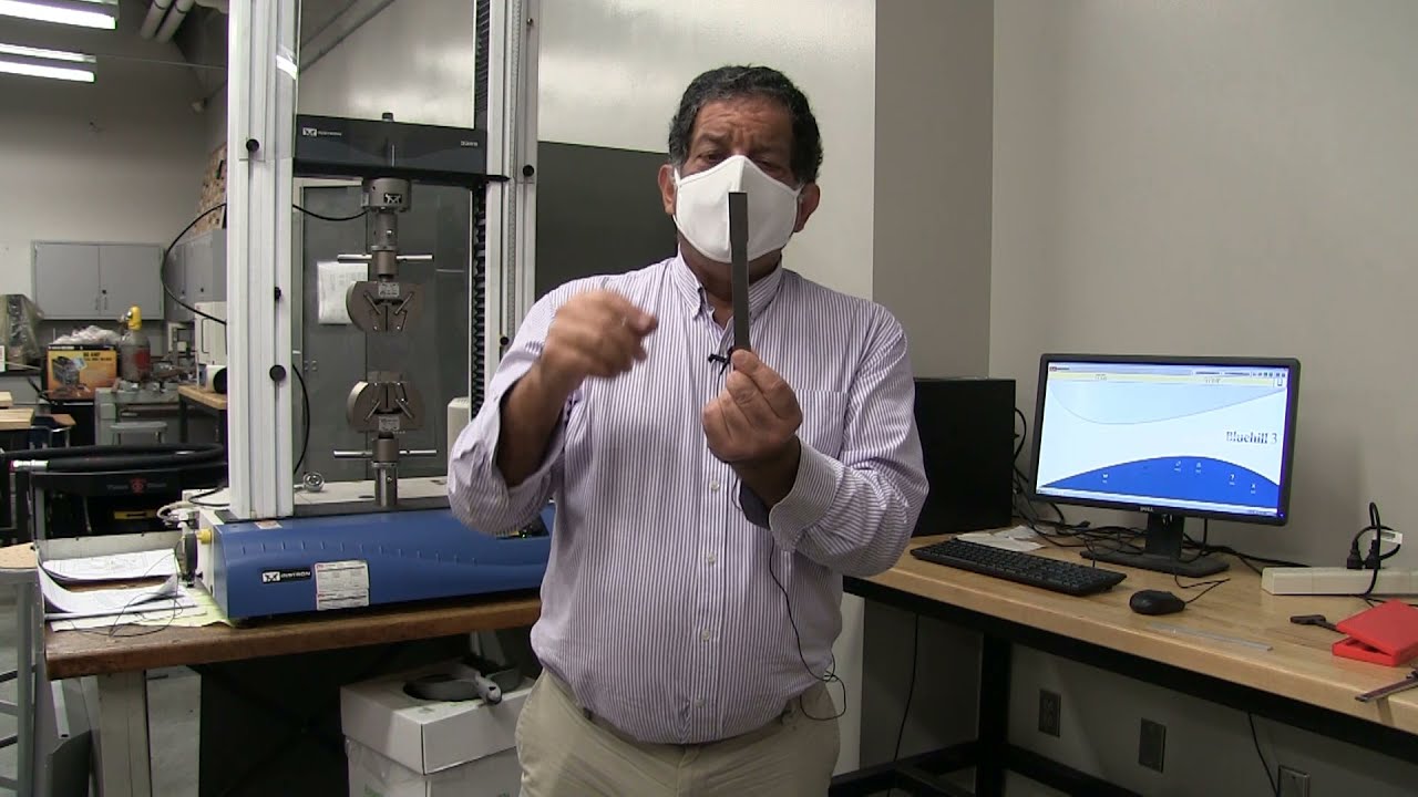
The Cal Poly Pomona laboratory video below demonstrates a general tension test. It helps illustrate controlled axial loading and specimen observation. It does not show an insert-specific fixture or establish extraction criteria; those details belong in the approved pull-out protocol.
The demonstration is listed in the university’s materials laboratory course resources. Use it to understand the loading principle while keeping the insert and substrate test specific to the application.
Ask for insert and host identity, revisions, material lots, measured hole and coupon dimensions, installation records, conditioning, fixture description, machine and load-cell verification, loading rate, engagement, individual curves, endpoint values, failure photographs and final disposition. Clearly identify development specimens separately from production-lot verification.
TNHO’s knurled insert family illustrates relevant product geometries. The thread-insert selection guide provides broader design context, while the first-article inspection guide and dimensional inspection guide help structure the records. A product photo or generic insert catalog cannot establish pull-out performance in an unspecified host.

No. The substrate, hole, installation, surrounding geometry, conditioning and loading method all contribute to the result of the tested connection.
Not without engineering analysis and an approved basis. Service loading, variability, environment, duration and design margins must be considered.
Record that failure mode. It may limit what the test establishes about extraction resistance and may require a different approved load-transfer connection.
They need matching specimen, installation, conditioning, fixture, loading and evaluation conditions, plus traceable instrumentation and complete individual results.

 TNHO
TNHO