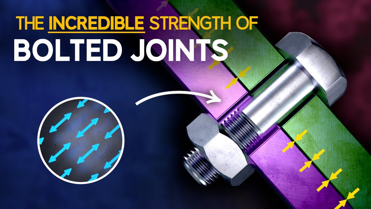
Joint clamp load testing measures the compressive force created when a fastener is tightened and retained across the clamped members. OEM teams use it to verify that an installation method produces the required preload, compare fastener finishes or lubricants, and check whether a joint loses force under service conditions. Torque alone does not directly measure clamp load. A reliable test must reproduce the production bolt, nut or tapped hole, washer, surface finish, stack, tool, tightening sequence, and environment.
As a bolt is tightened, it stretches and compresses the joint. The resulting axial bolt tension and member compression form the clamp load. A test records that force directly or estimates it from fastener elongation using a validated relationship. The result can be correlated with applied torque, angle, or another assembly control parameter.
The ISO 16047 torque/clamp-force test standard defines conditions for testing covered threaded fasteners and related parts. Its scope has limits by material, thread, size, and fastener type, so first confirm applicability. NASA’s torque-tension testing report for flight hardware describes how lubricant, inserts, and bearing friction can change the torque-to-preload relationship. Those measurements are tied to the tested hardware and should not be applied as universal values.

Choose an instrument based on required accuracy, access, sample size, joint geometry, service temperature, and whether testing occurs during production or in a laboratory. Direct-force methods measure the response closest to clamp load. Elongation and strain methods estimate force through calibrated fastener behavior. Each method changes or observes the assembly differently.
| Method | What it measures | Strength | Limit to control |
|---|---|---|---|
| Instrumented load washer or load cell | Compressive force through a sensor in the stack | Direct, time-resolved force measurement | Sensor thickness, stiffness, calibration, contact face, and alignment |
| Ultrasonic bolt elongation | Change in acoustic travel time or bolt length | Can evaluate an installed fastener without a special washer | Material calibration, end-face condition, temperature, access, and coupling |
| Strain gauge on fastener | Local strain converted to axial force | Useful for research and instrumented assemblies | Gauge placement, wiring, calibration, bending, and surface preparation |
| Torque-angle or torque trace | Installation response used as a correlated proxy | Works with production tooling and captures process signals | It remains indirect and depends on friction, seating, and joint stiffness |
| Direct tension indicator | Fastener tension or gap response at a designed indicator | Can support installation verification in applicable designs | Indicator type, seating, bearing geometry, and acceptance criteria |
The table compares measurement approaches qualitatively. Instrument range, calibration uncertainty, fixtures, and acceptance bounds must be set from the test plan and joint risk.
Use production-intent parts: the actual fastener standard, material and property class, coating, lubricant, nut or internal thread, washer, plate material, hole, grip, and surface finish. Match the installation tool, socket, speed, tightening sequence, and environment. If an instrumented washer is inserted, account for its thickness and stiffness because it changes the stack and bearing interface.
Check that the fixture loads the joint axially and does not introduce unintended bending or eccentricity. The plate stiffness, support locations, and hole clearance should resemble the application. A rigid laboratory coupon can produce a different torque-tension response than a thin enclosure wall, flexible bracket, or gasketed assembly.
NASA-STD-5020, Requirements for Threaded Fastening Systems in Spaceflight Hardware, is an active NASA standard that addresses installation control and threaded joint design within its spaceflight scope. Use it for applicable work and as a reference for the need to test the actual fastening system, not as a substitute for the OEM’s governing code.
Define sample conditioning, instrumentation calibration, part identification, and the target fastener condition before testing. Install the joint using the released sequence. Record torque, angle, clamp load or elongation, rundown behavior, seating point, tool speed, and temperature. If the test evaluates preload retention, continue measurement through the specified dwell, temperature cycle, vibration profile, or service sequence.
Repeat the test across representative lots and configuration changes. Include the approved lubricant and coating condition; do not silently substitute a dry or polished sample. Preserve individual results and traces. Report the distribution, measurement uncertainty, exclusions, failure modes, and acceptance decision. A single average can hide a wide spread or distinct process groups.
Before loading a sample, verify the instrument calibration, tare condition, range, sampling rate, and fixture alignment. Confirm that load is applied through the intended bearing faces rather than through a cable, sensor edge, or unintended contact point. Document whether the nut or bolt head is rotated, because rotating one side versus the other can change the torque-tension response.
Build a test matrix around the variations that can reach production: fastener lot, mating thread, lubricant, washer, coating, tool, and assembly speed. Avoid changing several variables together if the goal is to isolate their effect. Decide the sample plan, acceptance bounds, and outlier rules before reviewing results. Preserve raw time-series data where available so seating, stick-slip, torque spikes, and relaxation can be examined.
For retention testing, record the initial force, dwell period, temperature history, and any vibration or transverse load sequence. The sensor must remain within its calibrated operating range throughout. If the fixture uses a rigid plate stack but the product uses thin formed sheet, run an additional test with representative production geometry rather than assuming the stiff fixture captures the same behavior.
This engineering explainer covers preload and joint stiffness, providing context for force measurement. It is not a clamp-load test procedure and does not set product acceptance limits.

Set a target clamp-load range from the joint function and design limits. Compare each candidate torque, angle, or tool signature against measured force. Determine whether the lower bound maintains sealing, friction grip, or joint integrity and whether the upper bound avoids yielding, thread stripping, crushing, and component distortion. Include measurement uncertainty and process variation in the decision.
If the measured spread is too broad, investigate friction, lubrication, coating, tool behavior, fixture compliance, and part variation. Do not simply widen the torque window without checking both minimum and maximum clamp load. Alternative controls may include improved surface consistency, a direct force indicator, angle control correlated to tension, or a redesigned joint.
Revalidate when the supplier, fastener finish, washer, lubricant, material, tool, or assembly sequence changes. Keep an approved test report with the drawing, process specification, lot traceability, and revision record.
Errors include using a sensor whose thickness changes the bearing system without adjusting the fixture, measuring torque but calling it clamp force, omitting the production lubricant, failing to zero or calibrate instrumentation, and ignoring bending. Another common problem is comparing results from different test rigs without matching stiffness and contact geometry.
Do not extrapolate a result outside the tested size, material, coating, thread type, or temperature range unless engineering analysis supports it. A preload test does not by itself prove vibration durability, fatigue life, corrosion resistance, or long-term gasket performance; those require the relevant application tests.
Separate measurement uncertainty from part-to-part variation. A noisy or drifting sensor can make a consistent fastener look variable, while a precise fixture can still miss a manufacturing subgroup if the sample selection is biased. Include a reference check and verify the assembly sequence before attributing an unexpected reading to the supplier. Record fixture and software revisions because they are part of the test method.
When reporting results, state whether values are measured directly or inferred from elongation, the torque instrument and resolution, the fastener and mating-part lots, the conditioning process, and the exact fixture drawing. Include individual values, an agreed summary of variation, exceptions, and the decision against the preapproved acceptance window.
TNHO’s hex and square-head bolt family illustrates relevant fastener geometries. For bolt strength and property markings, see the hex bolt grades guide. The torque-tension guide explains the indirect conversion, while the friction coefficient guide describes surface variables. State the complete test configuration and required report on the RFQ.
No. Torque is a tightening input. Clamp load is the compressive force developed in the joint. Friction and geometry cause substantial variation, so correlate torque to measured force for the specified assembly.
An instrumented load washer or load cell measures force through a sensor in the stack. It changes the stack, so include its thickness, stiffness, and bearing faces in the test design. Ultrasonic and strain methods can measure elongation or strain as calibrated proxies.
No. A torque wrench can control applied torque, but friction variation can change the clamp load. Use representative force or elongation measurements to establish the installation process.
Repeat tests when the fastener, coating, lubricant, washer, mating material, tool, fixture, or installation sequence changes, and at intervals defined by the quality plan and application risk.

 TNHO
TNHO