Why screws loosen under vibration depends on how the whole joint moves and retains clamp force. Repeated relative movement at the bearing surfaces and threads can permit rotation, while settlement, relaxation or thermal changes can reduce preload without initial rotation. Preventing loosening starts with a suitable joint, controlled installation and retained clamp force, followed by a locking method validated for the actual assembly. Selecting a screw drive or adding an unspecified washer does not answer those questions. OEM buyers should define the load, materials, thread engagement, surface condition and service environment before approving a retention solution.
A loose screw is an observation, not a complete failure diagnosis. A joint may lose clamp force because rough surfaces settle, a soft layer creeps, a gasket relaxes, or temperatures change the relative expansion of the parts. The screw may remain at nearly the same angular position during those changes. Rotational self-loosening is another mechanism, in which repeated joint movement permits the threaded fastener to unwind.
The distinction changes the remedy. A rotational restraint may limit unwinding but cannot necessarily restore clamp force lost through a compressible layer. Conversely, changing a gasket or tightening process may improve retained preload while leaving a transverse-motion problem unresolved. Record whether the symptom is reduced clamp force, visible rotation, a changed seating condition, fretting, separation or another sign.
Do not diagnose the mechanism from a witness mark alone. A mark can help track relative rotation, but it does not measure clamp force. Similarly, a later breakaway-torque reading is affected by friction and surface condition. Use an investigation or test method that measures the property the design actually requires.
Preload clamps the mating parts together and establishes the contact conditions through which a bolted connection carries load. If the applied load and joint design permit relative sliding, the conditions at the bearing face and engaged threads can change repeatedly. Transverse excitation is therefore an important consideration when evaluating self-loosening, alongside axial loading, joint stiffness and retained preload.
Gerhard Junker’s SAE paper on self-loosening under vibration discusses the theory, design guidance and quantitative testing of locking properties. It is a useful research reference for treating loosening as a joint-and-test problem rather than selecting a retention feature from appearance alone. The correct test still needs to represent the intended fastener and application.
Not every vibrating assembly experiences the same motion at a particular screw. A housing may vibrate while the clamped interface remains stable, or a local flexible feature may move considerably more than the overall assembly. Describe the actual load direction, amplitude, frequency and duration, plus the permitted motion and failure criterion. A general vibration label is not enough to define validation.
Review the material stack, bearing surfaces, hole fit, grip length and engaged thread. Soft or poorly supported components can create a different preload-retention problem from a rigid metal joint. A screw that bottoms in a blind hole can also produce tool torque without the intended seating and clamp condition. Check those geometric conditions before selecting a locking device.
Evaluate stiffness and load transfer at the assembly level. The design should account for the screw, the clamped members, the mating thread and the external loads. Larger preload is not automatically an acceptable remedy: fastener proof requirements, tapped-hole strength, bearing pressure and deformation of the joined parts limit the installation. The responsible engineer must determine the target and permissible range.
The NASA Fastener Design Manual provides background on fastener selection, preload and locking concepts. Its examples support engineering review, but they are not a substitute for the customer’s governing standards or validation of a meter, enclosure or PCB assembly.
| Observed condition | Possible concern | Useful check | Control to evaluate |
|---|---|---|---|
| Angular movement at the screw head | Rotational self-loosening or installation movement | Track rotation together with joint motion and retained force | Joint slip control and a validated retention method |
| Clamp force falls with little rotation | Settlement, creep or relaxation | Measure force versus time and inspect the material stack | Stack design, bearing support and preload retention |
| Torque reached before the head seats | Bottoming, interference or damaged thread | Check hole depth, engagement and seating | Drawing dimensions and assembly controls |
| Fretting or movement at the joint | Repeated relative motion | Inspect contact surfaces and measure the applied motion | Load path, stiffness, preload and qualification testing |
| Result changes after a finish substitution | Changed friction or locking behavior | Repeat installation and retained-force validation | Coating, lubricant and supplier-change control |
The table identifies investigation routes. It does not diagnose a failed joint without measurements or prescribe a universal locking feature.
Specify the screw, mating thread, washer or bearing face, coating, lubricant, tool, speed and tightening sequence as one installation system. Torque is influenced by friction, so changing a finish or adding oil can change resulting preload at the same wrench setting. A process validated for one configuration should not silently be applied to another.
ISO 16047 defines conditions for torque/clamp-force testing of covered threaded fasteners. Where applicable, that type of evidence can help establish installation behavior. Verify the standard’s scope, particularly when the product has a locking feature or forms its own thread. Installation testing and service-vibration testing answer different questions and may both be required.
Calibrate and verify the assembly equipment under the approved procedure. Include checks for wrong screws, cross-threading, insufficient engagement, bottoming and head seating. If a screw is installed into plastic or a fragile component, define the acceptable process window against both clamp requirements and substrate damage. Do not raise torque after a field issue without reviewing those limits.
Mechanical retention, prevailing-torque features and chemical thread-locking products work through different mechanisms. Their suitability depends on serviceability, temperature, chemicals, substrate strength, reuse and the required retention behavior. The selected feature should be stated on the drawing or purchase specification, including the approved product or process and any installation conditions.
A locking patch can introduce prevailing torque during installation. That contribution must be considered when establishing the tightening method and target clamp force. A thread-locking adhesive can require controlled cleanliness, compatibility, application and cure conditions. A mechanical locking arrangement may also need a specific mating geometry or inspection. None should be qualified solely because it feels harder to turn by hand.
For serviceable assemblies, define whether fasteners or retention elements can be reused. Repeated assembly can change thread condition, coating and locking behavior. If reuse is allowed, test the intended number of service operations under the approved method and document replacement criteria. A first-installation result cannot establish performance after repeated disassembly.

Start with an application test plan describing the fastener and joint, imposed loading, environmental conditioning, duration, assembly procedure and acceptance criteria. If a standardized transverse-displacement test is selected to compare locking behavior, document its method and limits. A comparison on a test fixture should not be reported as proof of every service condition.
Choose measurements that distinguish failure modes. Track angular movement, retained clamp force, joint separation, damage and any relevant electrical or functional change. For an enclosure or terminal assembly, the acceptance criteria may include conditions beyond whether the screw remains physically present. Record test interruptions and process deviations rather than excluding them from the report.
Use production-representative parts and surface conditions. A prototype with a different screw grade, finish, plastic, washer or locking treatment can behave differently from the production joint. Confirm the lot and configuration, and review substitutions with the engineering authority before using the test as qualification evidence.
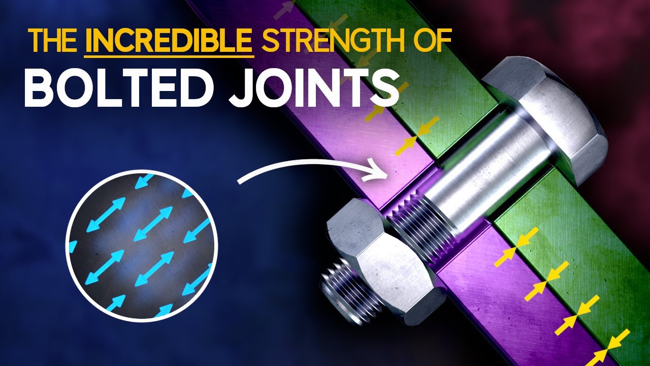
The Efficient Engineer’s explanation below illustrates preload and how bolted joints carry load. These principles help establish the starting conditions for a loosening investigation. The video is a learning aid; it does not provide a vibration specification or approve a retention method for an individual assembly.
For sourcing, TNHO’s hex socket screw family illustrates available geometries and optional retention configurations. Use the torque–tension guide for installation context, the preload-loss guide for settlement and relaxation, and the cross-threading prevention guide for assembly controls.

No. The result depends on joint motion, preload and contact conditions. Clamp force can also fall through settlement or relaxation with little rotation, so measure the actual symptom.
Only if the engineering review establishes an appropriate installation change within fastener, thread and substrate limits. Increasing torque without checking the joint can damage parts or leave the underlying mechanism unresolved.
No. A retention feature and the installation process must be evaluated together. Prevailing torque can affect the relationship between tool torque and resulting clamp force.
Identify the fastener, joint, finish, assembly method, imposed loading, environment, duration, measured outcomes, acceptance criteria and lot records. State limitations of any standardized fixture comparison.

 TNHO
TNHO