Fastener dimensional inspection verifies that a bolt, screw, nut, washer, or insert matches the approved drawing and product standard. Choose an instrument for each characteristic rather than using a caliper for every measurement. A caliper can check accessible overall length or head width, but thread pitch diameter, runout, straightness, countersink angle, coating thickness, and functional fit may require gauges or specialized measurement. The inspection plan should define the datum, method, instrument, calibration status, sampling, units, and acceptance limits for every controlled feature.
Confirm the part number, drawing revision, nominal size, tolerance, unit system, thread designation, and measurement datum. For fasteners made to a recognized standard, identify the edition and verify which dimensions are supplied by the standard versus the controlled drawing. A nominal size alone is not a complete acceptance rule.
For metric screw threads, ISO 1502 specifies gauges and gauging for general-purpose metric threads. Use the correct thread class and gauge design for the fastener type. A functional gauge checks a defined fit condition; it does not report every thread dimension or replace required material and process documentation.

| Characteristic | Common inspection method | Key limitation to consider | Record on the plan |
|---|---|---|---|
| Overall length and head width | Caliper or micrometer from the defined datum | Head shape, edge burr, coating, and contact pressure affect readings | Datum, contact points, unit, tolerance, instrument ID |
| Major diameter and shank size | Outside micrometer or suitable optical method | Measure the functional surface and avoid thread crest or burr errors | Measurement locations, temperature, calibration status |
| Thread pitch and form | Thread pitch gauge, comparator, or optical system | A pitch gauge is a quick check, not full-form thread acceptance | Thread system, pitch, class, method, acceptance rule |
| Thread functional fit | Specified GO/NO-GO plug or ring gauge | Gauges must be correct, calibrated, and used per standard | Gauge ID, class, calibration date, result |
| Thread runout and incomplete threads | Optical measurement or defined functional check | Small transitions may be obscured by plating or underhead geometry | Start/end points, drawing note, allowable condition |
| Head angle or countersink | Optical comparator, angle gage, or CMM | Contact edges and datum alignment influence the result | Angle datum, method, instrument, tolerance |
| Coating thickness and surface | Approved coating test method and visual inspection | Base material, geometry, and measurement location affect readings | Finish spec, test method, lot, sampling frequency |
This table lists common approaches, not universal instrument tolerances. Use the drawing, product specification, and quality plan to select equipment with adequate resolution and measurement uncertainty.
A vernier or digital caliper can be useful for lengths, widths, and accessible diameters. Check zero before use, keep the jaws square to the part, and apply consistent contact pressure. Calipers may not resolve a close tolerance reliably and can bridge chamfers or touch thread crests unintentionally.
Micrometers provide controlled contact for many outside dimensions, but the operator must select the correct anvils and measure at specified locations. Small fasteners may require optical comparators or vision measurement when features are too small or complex for reliable manual tools. For internal threads, use a specified plug gauge or calibrated measurement method rather than a caliper reading across the opening.
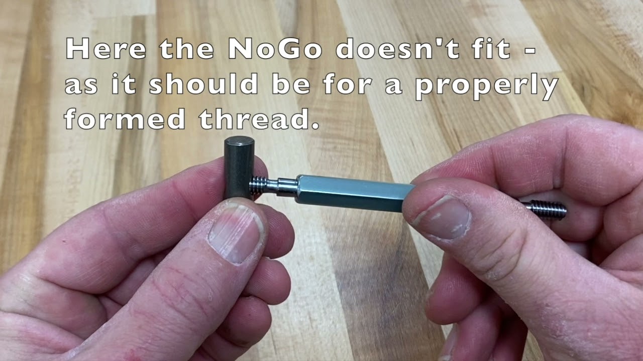
This manufacturing education video demonstrates a functional thread-gauge check. It covers one inspection method; the complete dimensional plan must follow the fastener drawing and selected instrument capability.
Thread gauges offer a functional check when used exactly as specified. Confirm the gauge belongs to the correct thread system, size, pitch, and class. Keep gauges clean and within calibration. Apply only the force allowed by the procedure; forcing a gauge can damage threads or produce a misleading result.
A GO/NO-GO result is not the same as recording pitch diameter, lead, flank angle, or coating thickness. If the drawing controls those dimensions separately, use an appropriate measurement method. The thread gauge inspection guide explains functional checks; the thread runout guide covers incomplete threads and transition details.
Inspection results are only useful when the instrument and method can resolve the tolerance. Maintain calibration traceability and use measurement standards or checks appropriate to the device. Allow parts and instruments to stabilize in the measurement environment when thermal expansion can matter. Remove loose debris but do not polish away a burr or coating defect before recording it.
Understand uncertainty at the tolerance limits. Tool resolution, repeatability, operator technique, datum alignment, surface roughness, part temperature, and calibration all contribute. If the measurement uncertainty is large relative to the tolerance, use a more suitable method or consult metrology support. The NIST metrological traceability guidance explains how measurement results connect through a documented calibration chain to recognized standards.

Set the sampling plan from the drawing, customer requirements, risk, process capability, and quality procedure. First-article and process-change inspections may require more characteristics or samples than routine lot checks. Keep the sampling method and acceptance numbers with the inspection plan rather than applying an unexplained default percentage.
When a result is out of tolerance, verify the drawing revision, setup, instrument, and measurement location before disposition. Preserve nonconforming samples and record actual readings. Do not average a failing dimension into conformance unless the approved statistical method explicitly permits that treatment. Corrective action should address the process cause and include reinspection of affected material.
Organize the inspection in the same order that a part is identified and handled. First confirm the lot label, part number, revision, and quantity against the purchase order. Separate samples from production material so an inspection part cannot be returned to the shipment unnoticed. Clean the part using the approved method and preserve the delivered surface condition; aggressive cleaning or polishing can hide a burr, coating defect, or damage that should be evaluated.
Before measuring, let the instrument and sample reach a stable environment when temperature can affect the result. Verify the instrument identification and status, check zero or reference standards, and confirm the correct units and range. Use a defined datum and contact location for each dimension. For example, measure overall length from the drawing’s specified bearing face to the thread end rather than choosing whichever edge is easiest to touch. Repeat readings only as the procedure directs and preserve the individual results.
Record results in a characteristic-by-characteristic format. Each row should state the drawing balloon or characteristic name, nominal dimension, upper and lower limits, measured value, unit, instrument or gauge ID, method, sample identity, and acceptance decision. For functional gauges, record the gauge type and identification, thread class, calibration status, and the prescribed GO/NO-GO outcome. A result without its method and part revision is difficult to reproduce or defend during a supplier corrective-action review.
Instrument selection should account for the tolerance width, feature size, accessibility, surface condition, and required decision confidence. A tool with fine display increments is not automatically accurate enough; calibration, repeatability, contact force, alignment, and operator technique also matter. If two inspectors obtain materially different results, compare their fixturing and datum interpretation, then assess whether a written method or a more suitable instrument is needed.
For close tolerances, discuss measurement uncertainty and the acceptance rule with the quality or metrology function before releasing a lot. Define what happens when a result lies close to a limit and whether guard bands or a specific decision rule apply. Do not invent a tolerance allowance after seeing the measurement. Any adjustment to limits or method needs approval from the authority named by the drawing, contract, or quality system.
Maintain a clear link between the instrument and its calibration record. A calibration label alone may not show scope, range, or uncertainty for the feature being measured. Confirm that the instrument was calibrated for the relevant range and that any required intermediate checks were current at the time of inspection. If equipment is found out of tolerance, follow the documented impact review for measurements made since its last known acceptable state.
Provide the drawing and revision, applicable product standard, critical dimensions, thread class, material and finish, post-coating condition, functional gauges, calibration requirements, sample plan, reporting units, lot traceability, and acceptance criteria. Identify special features such as slots, serrations, runout, captive washers, cross holes, or tamper-resistant drives.
TNHO’s hex and square-head bolt family illustrates the kind of product features that can require different inspection methods. For broader dimension references, use the screw measurement guide and the hex bolt grades guide. The drawing and contract define the acceptance criteria.
No. They can measure some accessible lengths, widths, and diameters, but thread pitch diameter, functional thread fit, small runout, coating thickness, and complex head geometry may need gauges or other instruments.
It verifies a functional condition defined by the gauge and thread specification. It does not report every geometric thread feature or replace other required measurements.
Coatings can change finished size and fit. Measure before or after coating according to the drawing and coating specification, and state which condition the acceptance limits cover.
Record part and revision, characteristic, nominal value, tolerance, actual result, unit, method, instrument ID, calibration status, sample or lot, operator, and disposition.

 TNHO
TNHO