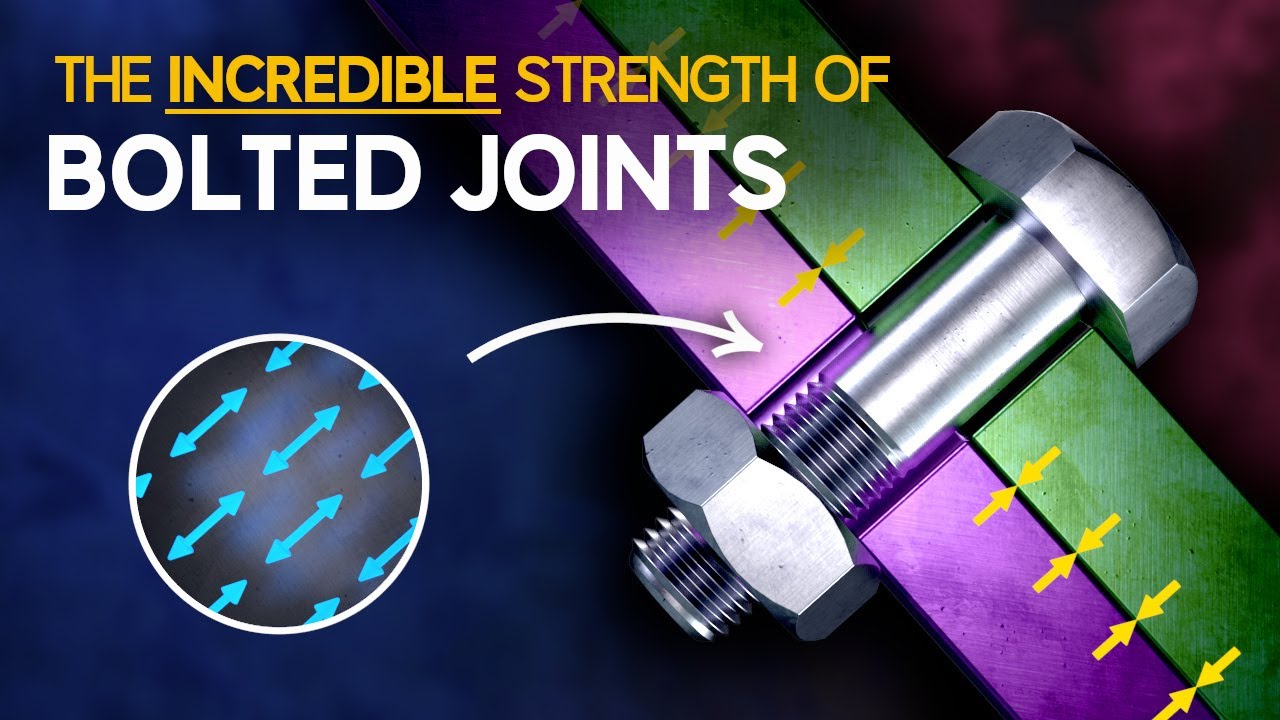
The torque-tension relationship in bolted joints describes how tightening torque produces bolt preload, or tension that clamps the joint. Torque is an indirect installation control because most of its work overcomes friction in the threads and beneath the rotating bearing face. The same wrench setting can therefore produce different clamp loads when finish, lubricant, washer, nut, tool, or assembly speed changes. Engineers should specify the complete fastener condition, define the target joint behavior, and validate the production combination instead of treating torque as a direct measurement of tension.
Applied torque is a moment that turns the nut or bolt. As the threads advance, the fastener stretches elastically and compresses the clamped parts. That elastic stretch creates preload. In a simple joint with no external separating load, bolt tension and member compression are approximately equal and opposite. Real assemblies also include joint stiffness, local embedment, gasket behavior, surface roughness, and possible bending or eccentricity.
The NASA Fastener Design Manual covers torque, preload, fastener groups, thread engagement, fatigue, and friction variables. It emphasizes that a joint needs an engineering design basis. A target preload should come from the joint function and limits, not merely from a table that lists a torque by bolt diameter.

A common approximation is T = K × D × F. Here T is applied torque, D is nominal fastener diameter, F is target preload, and K is an effective torque coefficient that represents friction and geometry for the defined assembly condition. For SI units, torque may be in newton-metres, diameter in metres, and force in newtons. For inch-pound units, use inch-pounds, inches, and pounds-force consistently.
This relationship is useful for organizing assumptions and comparing configurations, but K is not a universal material constant. It changes with thread and bearing friction, lubrication, coating, surface finish, washer size, and contact geometry. A calculated value is a candidate for testing, not proof that a production joint reaches the target tension.
ISO 16047 specifies conditions for torque/clamp-force tests on defined threaded fasteners and related parts. Its scope covers specified steel fasteners and thread sizes, with exclusions for certain self-locking or self-forming parts. Engineers should consult the complete standard and verify scope before applying it to a particular product.
During tightening, torque is consumed in three interacting ways: turning the thread against friction, sliding the bearing face under the nut or bolt head, and stretching the fastener while compressing the joint. The proportions depend on the assembly. A change in either friction interface can substantially alter preload without a visible change to the fastener.
| Torque-tension input | Effect on the relationship | What to define or test |
|---|---|---|
| Thread finish and lubricant | Changes friction as mating thread flanks slide | Coating, topcoat, lubricant type, amount, and cleanliness |
| Bearing face or washer | Changes friction and local contact pressure | Head or nut geometry, washer material, hardness, and finish |
| Fastener diameter and pitch | Changes thread geometry, stress area, and load capacity | Standard, size, pitch, class, and dimensional tolerances |
| Joint stiffness and grip | Changes elastic load sharing and response to external load | Member material, thickness, stack, and support geometry |
| Tool and tightening speed | Changes dynamic overshoot and repeatability | Tool type, calibration, rundown speed, socket, and sequence |
| Reuse or prior seating | Changes friction, embedment, and surface condition | Single-use policy or tested reuse and retightening procedure |
The table is qualitative and does not provide a universal torque value. Limits must come from the drawing, the governing design method, and validation on production-intent parts.
A calibrated torque tool can deliver the requested torque accurately while preload still varies. Tool calibration controls torque measurement, but it cannot remove friction variation in threads or under the bearing face. A click wrench, electronic nutrunner, impact tool, and hand wrench may also differ in speed, inertia, signal processing, and behavior on soft versus hard joints.
When clamp load is critical, validate the chosen torque method against measured tension. Suitable approaches can include an instrumented load washer, a calibrated tensile fixture, ultrasonic bolt elongation, strain measurement, or a documented torque-tension test. The fixture itself changes stiffness and bearing conditions, so correlate it with the actual joint.
This independent engineering explainer shows how preload and joint stiffness influence bolted-joint strength. It complements, but does not replace, application-specific testing.
Preload keeps the joint members compressed and can reduce separation, slip, and fluctuating bolt stress. Too little preload can permit movement, fretting, leakage, fatigue, or loosening. Excessive preload can yield the bolt, strip internal threads, crush a gasket or soft member, dish a washer, or distort a component. The allowable range is set by the weakest relevant part and the service load, not by bolt grade alone.
Under an external axial load, the bolt and clamped members share incremental load according to their stiffness. If the joint separates, the bolt can receive a much larger portion of added load. For cyclic loading, evaluate preload retention, joint separation, eccentricity, bending, and fatigue. The thread engagement guide covers internal-thread strength and stripping risk, while the fastener friction coefficient guide focuses on the friction inputs.
Begin with the complete configuration: bolt and nut standard, diameter, pitch, grade, coating, topcoat, lubricant, washer, mating material, engagement, and joint stack. Define the required clamp load or functional acceptance criterion. Determine the fastener and component strength limits, then choose a candidate tightening method and torque range based on verified engineering data.
Test multiple production lots and include realistic assembly tools, tightening speeds, and operators or automation conditions. Record applied torque, angle if applicable, achieved tension or clamp load, seating behavior, and failures. Use enough samples to understand scatter. The number of test joints and acceptance bounds should follow the product’s risk and quality plan.

Publish the released setting with a clear configuration ID, tool, sequence, tolerance, revision, and reaction plan. Revalidate when any part of the friction system or assembly changes. A supplier or finish substitution can invalidate the old relationship even when the bolt dimensions match.
Frequent errors include using dry torque on a lubricated bolt, assuming stainless and carbon steel fasteners share a torque table, ignoring the washer, counting prevailing torque as clamp-producing torque, and tightening a bolt into a soft threaded part using a steel-joint value. Another mistake is interpreting residual removal torque as a direct measurement of the original preload.
If a joint is safety-critical or highly variable, consider a more direct control such as measured elongation, angle control correlated to tension, direct-tension indicating devices, or in-process load measurement. Each method has its own limits, but it can reduce dependence on an uncertain friction estimate.
Turn-of-nut and torque-angle methods use measured rotation after a defined seating point to control fastener stretch. They can reduce sensitivity to some friction changes after seating, but they still depend on accurate joint geometry, a known snug condition, elastic behavior, and an assembly process that does not damage the threads. A calibrated angle tool also does not prove the member stack has seated as intended. Establish the procedure through calculation and validation for the actual joint.
Direct-tension indicators and load-sensing washers measure a response closer to clamp force, although the indicator itself changes the stack and must be included in the design. Ultrasonic elongation methods require material and length calibration and access to suitable measurement surfaces. Choose a method based on risk, accessibility, process capability, and the cost of an undetected preload error. Whatever method is chosen, define acceptance limits and reaction steps before operators begin production.
TNHO’s custom bolt product family illustrates how head, thread, and finish are selected for different assemblies. The hex bolt grades guide provides an upstream reference for strength classes. For a practical development sequence, use the screw torque chart guide and the related friction coefficient article. State the complete fastener and joint condition on an RFQ rather than requesting a standalone torque figure.
No. Torque is the input used to turn the fastener. Bolt tension is created by elastic stretch and is strongly influenced by friction, geometry, finish, lubricant, and the bearing interface.
Thread and bearing friction vary among finishes, coatings, lubricants, washers, nuts, tools, and assembly speeds. When friction changes, a different share of the applied torque becomes fastener tension.
Use a suitable, calibrated method such as an instrumented load washer, tensile fixture, ultrasonic elongation, or strain measurement. Validate the method against the actual joint because test-fixture stiffness and bearing geometry can alter results.
Not without review and, where needed, retesting. Coating and topcoat changes can alter thread and bearing friction, so the previous torque may produce a different preload.

 TNHO
TNHO