A screw torque chart is safe only when it is tied to a defined fastener, joint, finish, lubrication condition, and required clamp load. Diameter and strength class set important limits, but they do not determine one universal torque. Most applied torque is consumed by friction in the threads and beneath the head or nut; relatively little becomes useful bolt tension. A value copied from a generic table can therefore under-clamp a dry rough joint or overload a lubricated one. Use charts as controlled starting points, then validate the actual production assembly and document the conditions behind every value.
Torque creates rotation. The engineering objective is usually preload: the axial tension that clamps the joint. The conversion depends on nominal diameter, pitch, tensile area, thread geometry, material strength, friction, bearing diameter, surface finish, joint stiffness, and tool behavior. Changing zinc plating to black oxide, adding oil, replacing a washer, or tightening into a different nut can change the resulting clamp load even when the wrench setting stays unchanged.
The NASA Fastener Design Manual explains preload, torque-tension uncertainty, joint stiffness, fatigue, and thread engagement. It supports a process-based approach: define the required joint behavior first, then qualify an installation method. It does not provide permission to apply one table to every product.

Start with the fastener standard or drawing, diameter and pitch, property class or grade, material, heat treatment, finish, lubricant, thread-locking product, nut or tapped-hole material, engagement, washer, and head bearing geometry. Then define target preload or joint performance, the permissible fastener utilization, installation tool, tightening sequence, reuse policy, and service environment.
Separate nominal engineering assumptions from production controls. A design calculation may use an assumed friction range; production needs a purchase specification and test method that make that range realistic. If finish suppliers, lubricants, or mating hardware can change, the chart must identify those configurations rather than hiding them under one fastener size.
| Chart field | Why it matters | What must be controlled |
|---|---|---|
| Diameter, pitch, grade | Defines geometry and mechanical capacity | Standard, marking, certificate, thread class |
| Finish and lubrication | Changes thread and bearing friction | Coating system, topcoat, oil, cleanliness, lot condition |
| Bearing interface | Changes friction and local pressure | Head or nut face, washer, mating material, roughness |
| Engagement | Controls internal-thread stripping risk | Usable full-form depth, material, hole condition |
| Target clamp load | Links installation to joint function | Engineering basis, tolerance, verification method |
| Tool and sequence | Affects delivered torque and load distribution | Calibration, rundown speed, socket, passes, operator method |
| Reuse condition | Friction and damage change after cycling | Single-use rule or validated reuse limit |
This decision table deliberately contains no torque values. Values require verified material data, friction assumptions, and application testing.
A stronger fastener can often carry more preload, but the joint may not. Thin sheet, aluminum threads, plastic bosses, gaskets, terminals, and coated surfaces can crush, strip, creep, or lose conductivity before the screw reaches a high percentage of its capacity. A torque chart should therefore be organized by complete joint configuration, not only bolt grade.
Do not infer strength from color or head marking alone. Confirm the governing standard, mechanical-property documentation, and applicable dimensions. Stainless steels introduce additional galling and friction considerations; brass and aluminum have different strength and deformation behavior. Heat treatment and thread manufacturing method may affect fatigue and installation response.
Lubrication normally reduces friction, so the same torque can create higher tension than in a dry joint. Some electroplated systems include sealers or lubricated topcoats that are visually subtle but mechanically important. Wax, oil, anti-seize, adhesive, prevailing-torque patches, and contaminated threads can all shift the torque-tension relationship.
State conditions explicitly: for example, as-received coated fastener with specified topcoat, approved nut finish, no additional shop lubricant, and defined washer. Never label a column simply “lubricated” without identifying the material and application. Where galling is possible, use an approved prevention method and verify that it remains compatible with preload and service requirements.
A commonly used simplified relationship is T = K × D × F, where T is tightening torque, K is an experimentally selected torque coefficient for the stated hardware condition, D is nominal fastener diameter, and F is target preload. In SI units use newton-metres, metres, and newtons; in inch-pound calculations use inch-pounds, inches, and pounds-force. The coefficient combines thread and bearing friction with geometry effects. It is not a universal material constant and must not be copied between finishes, lubricants, washers, or joint types without evidence.
For example, a design calculation starts with an approved target preload for a specified bolt and joint, selects the matching measured coefficient for the production finish and bearing parts, and computes a candidate torque. The result is then checked against fastener capacity, internal-thread strength, bearing limits, and validation-test data. This symbolic workflow provides a reproducible basis without implying an unsupported generic value. The ISO 16047 torque/clamp-force test standard defines conditions for measuring torque and clamp force on covered threaded fasteners; use the full standard and its applicability limits for a formal test plan.
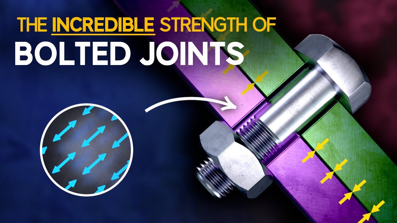
This independent engineering video explains preload and joint stiffness. It helps clarify why a torque chart must be connected to clamp load rather than treated as a standalone lookup.
Build representative assemblies using production fasteners, nuts or tapped parts, washers, finishes, and tools. Measure torque and achieved tension using a suitable load cell, instrumented joint, ultrasonic method, strain method, or another qualified technique. Include multiple lots and enough samples to understand variation. Record rundown, seating, final torque, angle, clamp load, and failure mode where relevant.
Choose a setting and tolerance that achieves the joint requirement without exceeding fastener, thread, bearing, or component limits. For multiple-fastener joints, validate the tightening sequence and elastic interaction. Recheck after process changes such as a new coating supplier, lubricant, washer, tool, or mating material.

A calibrated tool can deliver torque accurately while the joint still produces variable preload. Control socket fit, extension use, rundown speed, seating detection, soft versus hard joint behavior, and reaction forces. Pulse tools, click wrenches, electric nutrunners, and hand tools have different signatures and repeatability.
Use traceable calibration and a reaction plan for out-of-control results. If the product is safety critical, consider monitoring angle, torque trace, residual torque under a defined method, or direct tension. Residual torque is not automatically equal to installation torque and should not be interpreted without an approved procedure.
Give each row a configuration identifier. Include fastener part number, mating part, washer, finish, lubricant state, target and allowable installation range, tool, sequence, source test report, approval, revision, and effective date. Keep notes beside the applicable row instead of placing a broad disclaimer far from the value.
Separate development values from released production values. Retire obsolete revisions and prevent operators from using screenshots or uncontrolled printouts. Where several markets or plants use different fastener sources, qualify each approved combination or standardize the parts.
Common errors include mixing inch and metric hardware, using proof or yield strength as the target clamp load without joint analysis, ignoring lubrication, treating prevailing torque as clamp-producing torque, applying steel values to aluminum or plastic internal threads, and failing to account for washer or flange changes. Another error is publishing more decimal places than testing can support.
A chart should also avoid unexplained minimum, nominal, and maximum columns. Clarify whether limits apply to tool output, audit torque, or calculated preload. The FAA AC 43.13-1B offers general hardware practices, but equipment-specific drawings and approved instructions remain controlling.
TNHO’s custom bolt product family illustrates how head, thread, and finish vary by application. For a broader bolt specification reference, see the hex bolt grades guide. The torque-tension guide explains the underlying conversion, and the friction coefficient guide addresses finish and lubrication control. An RFQ should identify the exact fastener and test condition instead of requesting a generic torque value.
For supplier approval, request the governing product standard or controlled drawing, material and mechanical-property evidence, coating specification, lubricant designation, dimensional report, lot traceability, and any required coefficient-of-friction or torque-tension test results. Define the mating hardware used for testing so results from a reference nut are not silently applied to a different production thread. Packaging and handling also matter because oil loss, mixed lots, damaged threads, and contamination can change assembly behavior.
During incoming inspection, verify identity and condition before running confirmation tests. A torque audit should use the approved fixture, sample conditioning, tool, speed, and data method. If results shift, quarantine affected lots and investigate the fastener, mating part, finish, lubricant, and equipment together. Adjusting the tool setting without finding the cause can hide a process change and create another failure mode.
Use it only as an initial engineering reference. Production values should be validated on the exact fastener, finish, lubricant, mating thread, washer, joint material, and tool, then released under revision control.
Lubrication usually reduces friction, allowing more of the applied torque to create bolt tension. Keeping the dry torque after lubrication can produce excessive preload, thread damage, or fastener yielding.
No. A higher grade may permit higher fastener preload, but the internal thread, washer, sheet, gasket, terminal, or other joint component may govern. Design the complete joint.
Revalidate when fastener, finish, lubricant, mating part, washer, tool, supplier, or assembly process changes, and at the interval required by the quality plan or risk assessment.

 TNHO
TNHO