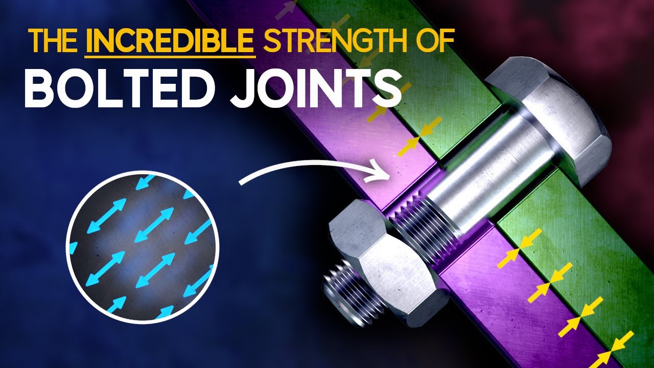
Bolt grip length is the unthreaded portion of a partially threaded bolt that passes through the clamped parts, and “grip” also describes the total thickness of the joint stack. Correct selection places the smooth shank through the intended bearing or shear region while leaving enough usable thread for the nut or tapped hole. If the grip is too long, the nut may bottom on the shank or thread runout before clamping the joint. If it is too short, threads may enter a shear plane or bearing hole and reduce fit quality. The design must cover the full production tolerance stack, not only nominal thickness.
On a bolt drawing, grip length normally means the distance from the underside of the head to the start of the thread or thread runout, depending on the applicable definition. In joint design, grip or grip thickness often means the total clamped material between the bolt head bearing face and nut or tapped support. These values are related but not identical. A successful selection compares both with the standard’s thread length, runout, washers, and assembly tolerances.
Always identify the measurement datum. Countersunk fasteners, flange heads, rounded heads, and special underhead forms may use different length conventions. The pictured reference is a custom long round-head bolt with a longitudinally knurled grip and a short threaded end. Its geometry should not be generalized to an ordinary hex bolt without a drawing.

A smooth or controlled shank can provide a continuous bearing surface through a hole and a larger cross-section than the thread root. In a joint designed to bear on the fastener after slip, keeping threads out of the shear plane can improve contact and simplify analysis. A controlled shank can also locate parts more repeatably than thread crests, although a precision locating or pivot function may require a shoulder screw, fitted bolt, or dowel rather than a standard commercial bolt.
In a properly preloaded slip-resistant joint, friction between clamped surfaces may carry normal transverse load. Grip geometry still matters because it influences bolt stiffness, runout location, assembly, and behavior if slip occurs. The NASA Fastener Design Manual explains the relationship among preload, stiffness, fatigue, and joint load transfer.
| Grip selection check | If too short | If too long | Required verification |
|---|---|---|---|
| Shear-plane position | Threads may cross the plane | Smooth shank may extend into nut or tapped thread | Locate every potential plane at minimum and maximum stack |
| Nut run-down | Usually more thread is exposed | Nut can bottom on shank or runout | Confirm full seating and engagement on worst-case parts |
| Bearing in holes | Thread crests contact the hole | Shank may fit, but stack cannot clamp | Check shank diameter, hole clearance, runout, and joint closure |
| Washer changes | Removing a washer can move thread into the joint | Adding washers may be used incorrectly as a spacer | Control the approved washer stack and service configuration |
| Tolerance variation | Thin stack may expose more thread | Thick stack may consume usable thread | Perform worst-case stack-up using actual limits |
| Future substitution | Different standard thread length changes grip | Same nominal length may not assemble | Specify grip or thread length, not only diameter and overall length |
The table provides failure logic rather than universal dimensions. Use the exact product standard or drawing and the full joint tolerance analysis.
List every clamped item in assembly order: plates, brackets, bushings, gaskets, spacers, and washers. Record minimum and maximum thickness for each. Sum the minimums to obtain the thinnest possible stack and the maximums for the thickest. Add effects that change after assembly only when the design method requires them, such as gasket compression or coating embedment.
Then compare both stack extremes with bolt grip, thread runout, nut height, usable engagement, and permitted protrusion. The thinnest stack is often the critical condition for a shank bottoming beneath the nut; the thickest is often critical for insufficient engagement. Do not “solve” an incorrect bolt by adding arbitrary washers unless that stack is engineered, documented, and controlled.
The transition between shank and thread contains incomplete threads or runout. A nut may start onto some of this region without providing normal full-form engagement, and a washer or plate can hang on the increasing thread profile. Product standards define thread length and transition geometry differently, so the drawing should show what dimension is controlled.
Provide relief or suitable clearance when a mating part must sit close to the thread start. Inspect for burrs and rolled-thread lead-in that interfere with seating. Our thread runout specification guide covers drawing language and inspection, while the thread engagement guide explains how material and internal-thread strength affect required engagement.
A longer elastic bolt length can change how external axial load is divided between the bolt and joint. This is one reason grip and joint stiffness appear in fatigue-sensitive bolted-joint analysis. The benefit cannot be reduced to “longer is always better,” because head seating, engagement, bending, shank diameter, thread location, and joint separation also matter.
This independent engineering video explains preload and joint stiffness, providing context for why grip is part of a system rather than an isolated catalog dimension.
For cyclic joints, analyze preload loss, separation, fluctuating bolt stress, bending from joint eccentricity, and the thread runout transition. Validate surface finish and manufacturing method when fatigue performance is critical. Rolled and cut threads, heat treatment, plating, and post-process handling can affect behavior; require the applicable standard and test evidence.
A single-shear joint has one interface where members can move relative to each other; a double-shear connection has two. Map each plane along the bolt axis. If the design intends smooth shank at all planes, the minimum shank coverage must extend beyond them at the maximum stack while still allowing clamping at the minimum stack.
Do not treat a knurled grip as a smooth bearing shank. Knurls may be designed for interference, anti-rotation, or retention and create a different hole interaction. The TNHO reference used in the images has longitudinal knurling, so its hole and installation process require product-specific limits. For ordinary partial-thread bolts, a cylindrical shank is more typical.

A nominal shank diameter does not guarantee a locating fit. Standard clearance holes intentionally allow assembly, and coating changes both hole and bolt dimensions. If the grip is used for alignment, specify shank limits, hole limits, true position, straightness, finish, and the installation sequence. Confirm that multiple holes are aligned enough to accept the bolt without hammering or damaging threads.
Forced installation can scrape plating, raise burrs, preload parts laterally, and make later removal difficult. A lead-in, controlled chamfer, or assembly fixture may help, but should not hide an incompatible tolerance scheme. For motion pivots, review the shoulder screw tolerance guide because an ordinary grip bolt may lack the required bearing precision.
Washers change the clamped thickness and the bearing interface. Include their actual thickness tolerances. A washer may be required for load distribution, slot coverage, surface protection, or a locking system; it should not be added casually to consume extra shank. If several washers are needed only to make the nut reach thread, choose a more appropriate grip length.
Specify the nut and engagement requirement together with the bolt. The required protrusion depends on thread lead-in, locking feature, governing standard, and inspection rule. A visible thread beyond the nut may help confirm engagement, but an arbitrary number of exposed threads is not a universal design calculation. Blind tapped holes require adequate full-form thread plus clearance so the bolt does not bottom before clamping.
Standard partial-thread formulas often change thread length with bolt diameter and overall length. Therefore, two bolts with the same nominal diameter and overall length but made to different standards can have different grips. A supplier substitution can move thread runout into the joint or prevent nut run-down even if the label looks equivalent.
Control the applicable standard and edition, or place the required grip and thread dimensions directly on the drawing. When an existing bolt is measured, identify whether length is taken from under the head or from another datum. The FAA AC 43.13-1B includes general hardware practices for aircraft maintenance, but the approved equipment instructions govern a specific replacement.
Specify thread size and class, overall length and datum, required grip or thread length, shank diameter and form, runout, head geometry, end form, cross holes if any, material, grade or property class, heat treatment, finish, marking, documentation, inspection, and traceability. Provide the minimum and maximum joint stack, shear-plane locations, hole limits, nut or tapped-hole details, and installation method.
TNHO’s knurled-shank carriage bolt product page shows a relevant custom long-grip family. Actual dimensions and performance remain drawing-specific. Incoming inspection should measure the correct datums, confirm usable thread, and perform a functional assembly check with controlled mating parts. Record actual results for first articles rather than only pass/fail.
No. Overall bolt length follows the applicable head-style datum, while grip length is the unthreaded portion or, in joint language, the thickness of the clamped stack. State which meaning is intended on calculations and drawings.
Often yes when the joint will bear on the bolt, because a smooth shank offers a continuous surface and larger section than the thread root. Some approved designs place threads in shear; calculate them using the correct section and governing standard.
Only when the washer stack is an engineered and controlled part of the joint. Adding arbitrary washers can alter bearing, preload, eccentricity, and service configuration. Selecting the correct bolt grip is normally preferable.
Provide minimum and maximum clamped stack, washer arrangement, shear-plane positions, required shank form and diameter, nut or tapped-hole engagement, thread runout allowance, overall length datum, material, grade, finish, and governing standard or drawing.

 TNHO
TNHO