The choice between partial thread vs full thread bolts depends on where the joint carries shear, how the parts locate, and how much usable thread is required. A partially threaded bolt places a smooth shank through part of the grip, which can provide a more stable bearing surface and keep threads away from a shear plane. A fully threaded bolt offers maximum adjustment and works well when grip thickness varies or the nut must travel farther. Neither style is inherently stronger in every assembly: diameter, grade, engagement, preload, geometry, and loading must be evaluated together.
A fully threaded bolt has external threads extending from near the head to the end, subject to the standard’s runout and end details. A partially threaded bolt has an unthreaded shank between the head and the threaded portion. The shank normally has a larger effective cross-section than the thread root and presents a smooth cylindrical surface to a hole. The transition from shank to thread includes thread runout, which must not be forced into a bearing location or interfere with seating.
The naming does not establish strength by itself. Two bolts must share the same material, heat treatment, diameter, applicable standard, and grade before a geometry comparison is meaningful. ISO 898-1 covers mechanical properties for specified carbon and alloy steel fasteners, but designers must use the edition and product scope required by the drawing. Inch fasteners may fall under different SAE, ASTM, or ASME requirements.

In a properly preloaded joint, friction between clamped members may carry normal service shear without the bolt bearing directly against the hole. If slip occurs or the joint is designed as a bearing connection, the portion crossing the shear plane matters. A smooth shank generally offers a larger, more uniform bearing surface than threads. Placing threads in a shear plane introduces thread roots, smaller tensile-stress area, and local contact effects. That does not automatically make a fully threaded bolt unacceptable, but the joint calculation must use the correct area and failure modes.
Axial tension is also geometry-sensitive. The threaded portion normally governs tensile capacity because the effective tensile-stress area is below the nominal shank area. A longer unthreaded shank may change fastener stiffness and load distribution. The NASA Fastener Design Manual provides background on preload, fatigue, stiffness, thread engagement, and combined loading. Use it as engineering guidance, not as a substitute for the project’s governing code.
| Selection factor | Partial-thread bolt | Full-thread bolt | Verification needed |
|---|---|---|---|
| Shear plane location | Smooth shank can be positioned across the plane | Threads may cross the plane | Calculate slip, bearing, shear, and fatigue for the actual joint |
| Grip-length variation | Limited by shank and thread start | Nut position is more adjustable | Confirm stack tolerance, washers, and full seating |
| Hole location or pivot bearing | Smooth shank may provide better bearing contact | Thread crests produce a discontinuous contact surface | Specify hole fit, shank diameter, wear, and lubrication if applicable |
| Thread engagement | Must leave enough thread after the grip | Usually offers more available threaded length | Check nut engagement and protrusion under worst-case stack |
| Runout interference | Thread runout can enter the hole or washer if poorly selected | Runout is near the head and may affect seating | Review standard dimensions and underhead clearance |
| Inventory flexibility | More grip-specific lengths may be required | Can cover more stack variations | Balance SKU reduction against joint performance |
This qualitative table supports selection but does not assign allowable loads. The responsible engineer must apply the relevant fastener and structural standards, load cases, safety factors, and material properties.
A partially threaded bolt is often preferred when the smooth shank should locate parts, bear against a hole, or cross one or more potential shear planes. Examples include clevis-style connections, machinery frames, and joints in which stable lateral alignment matters. The shank can also reduce abrasion compared with having thread crests rub against a hole, although a true precision pivot may require a purpose-designed shoulder fastener rather than an ordinary bolt.
Correct grip selection is essential. The shank should pass through the intended clamped thickness without preventing the nut from tightening. Conversely, the thread runout should not be trapped beneath a washer or inside a component where it stops the joint from closing. Drawing dimensions and tolerance stack-ups must cover the shortest and longest production conditions.
A fully threaded bolt is useful when the grip thickness varies, the assembly uses thin members, or adjustment along the fastener is needed. It may simplify purchasing because one length can accommodate several stacks. It is also common where the fastener threads into a tapped hole and the required engagement begins close to the head.
The tradeoff is that threads may lie in the bearing or shear region. If the joint can slip, use the threaded section’s applicable shear area and examine hole bearing, edge distance, fatigue, and fretting. Do not compare only catalog tensile strengths. A bolt that passes a static tensile check can still be unsuitable for cyclic transverse loading or a precision locating function.
Bolted joints usually perform best when installation creates enough preload to keep interfaces compressed under service load. The bolt’s thread coverage does not guarantee preload. Torque, lubrication, finish, thread condition, bearing surface, tool accuracy, tightening sequence, and relaxation all influence the result. For critical assemblies, establish the installation method through calculation and representative testing.
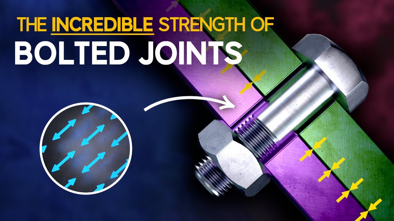
This neutral engineering video explains preload and joint stiffness, helping show why a bolt should be selected as part of a load path rather than by thread coverage alone.
Where fatigue is significant, consider how the fastener and joint stiffness divide an external load. Surface condition and thread runout also matter because geometric transitions can concentrate stress. Avoid field modifications such as cutting extra threads into a heat-treated bolt unless an approved manufacturing process and requalification explicitly allow it.
Start with the total clamped thickness, including production tolerances and any washers. For a partial-thread bolt, compare that range with the standard or drawing’s unthreaded grip length and thread runout. The nut must tighten before reaching the end of usable thread, and the unthreaded shank must not bottom in the nut. For a tapped hole, confirm usable full-form thread depth rather than counting a drilled depth that includes the tap point and incomplete threads.
Engagement requirements depend on the internal and external materials, thread form, strength, and loading. A simple “one diameter” rule is not universal, especially in aluminum, polymers, cast materials, or short nuts. The detailed thread engagement length guide explains the variables and drawing checks. If the application uses mixed inch and metric hardware, also review the metric versus imperial bolt guide to prevent near-fit assembly errors.
Hole clearance determines whether a shank truly locates the parts or simply passes through them. A standard clearance hole is not a precision bearing. If location, low play, or repeatable motion is required, specify the hole process, diameter tolerance, cylindricity, finish, and mating shank tolerance. A shoulder screw or dowel may be more appropriate.

Coatings also affect fit. A plated shank can be larger than the base dimension, while a coated hole can be smaller. Finish influences friction and therefore torque-tension behavior. If corrosion protection, electrical bonding, or appearance is important, specify the complete finish system and test the production combination.
An RFQ should identify the standard or drawing, diameter and pitch, nominal length, required thread length or grip, head style, property class or grade, material, finish, marking, documentation, and lot traceability. State whether the shank must cross a defined shear plane and provide the full stack tolerance. Do not rely on a supplier’s generic description of “half thread,” because standard thread length may vary with diameter and overall length.
Incoming inspection should verify length from the correct datum, thread size and class, usable thread length, grip length, runout, shank diameter, head dimensions, finish, and required markings. Mechanical properties require the specified test evidence; appearance alone is insufficient. TNHO’s partially threaded carriage bolt and hex-head bolt product show relevant geometries, but the approved quotation and drawing define the delivered configuration.
Not in every sense. A smooth shank has a larger cross-section than the thread root and can be advantageous across a shear plane, but overall capacity depends on grade, diameter, preload, engagement, joint geometry, and loading. Compare the actual failure modes rather than the labels.
It is often beneficial when the joint is expected to bear on the bolt, because a smooth shank provides a more uniform section and contact surface. Some designs legitimately place threads in the plane, but calculations and standards must use the correct threaded-section properties.
Only after checking shear area, bearing, fatigue, fit, preload, grip range, and the drawing requirements. Equal diameter, length, and grade do not guarantee functional equivalence when the original shank located parts or crossed a shear plane.
Provide the complete clamped stack and tolerances, required shank location, washer arrangement, nut or tapped-hole engagement, and governing standard. Confirm that the thread runout clears the joint and that sufficient usable thread remains at both stack extremes.

 TNHO
TNHO