Coupling nuts are elongated internally threaded fasteners used to join two male-threaded components, most often threaded rods or studs. Their length provides room for engagement from both ends, while the hexagonal exterior gives a wrench a controlled reaction surface. That simple description hides the real engineering questions: how much thread is engaged on each side, where the rod ends meet, what load passes through the joint, which nut property class is compatible, and how the assembly is prevented from rotating loose.
This guide explains how to specify a coupling nut without treating it as a generic long nut. For a product-based reference, see TNHO’s hex standoff and coupling nut range and the broader nuts and washers category.
A standard coupling nut connects two externally threaded parts of the same nominal diameter, pitch, thread form, tolerance system, and hand. Each member enters from an opposite end. Reducing coupling nuts connect different diameters or pitches, and special versions can combine right- and left-hand threads. Those variations must be called out explicitly; they cannot be inferred from overall length.
The nut transfers axial load through the engaged thread flanks. Load does not divide evenly among every thread. The first engaged threads usually carry the greatest share, and stiffness, pitch error, material, coating, and deformation affect the distribution. A longer body creates the possibility of more engagement, but body length alone does not prove capacity. The nut, both mating rods, and their engagement depths must be evaluated as one load path.
ASME B18.2.2-2022 provides general and dimensional data for inch-series coupling nuts as well as other square and hex nut types. Metric products may be ordered to a named dimensional standard or a controlled drawing. Never mix an inch dimensional standard, a metric thread, and an unrelated mechanical class without defining how the requirements fit together.

Both rods must match the nut’s thread system. For metric assemblies, specify nominal diameter, coarse or fine pitch, tolerance class, and thread direction. For unified inch assemblies, specify diameter, threads per inch, series such as UNC or UNF, class, and direction. A part that starts a few turns can still be mismatched, damaged, or outside tolerance.
Coating changes fit. Hot-dip galvanized rods generally require a compatible allowance or overtapped nut under the selected standard. Electroplating, zinc flake, paint, debris, or damaged thread crests can also raise installation torque. High running torque is not evidence of high strength; it may be cross-threading or interference. Use the specified GO/NO-GO gauges, as outlined in the thread gauge inspection guide.
Check the runout and incomplete threads on studs. Engagement should occur on complete, functional threads rather than on a transition zone. TNHO’s thread runout guide explains why a nominal threaded length is not always the same as usable engagement.
There is no universal rule such as “half the nut on each rod” that proves strength in every design. Equal engagement is a sensible assembly target for a symmetric connection, but required depth depends on the tensile capacity of the rod, internal and external thread materials, shear areas, property classes, tolerances, and any governing code. The design should make the preferred failure mode explicit.
For a tension connection, calculate or validate the internal-thread stripping capacity on both sides, the external-thread stripping capacity of each rod, the rod tensile capacity, and the net body capacity of the coupling nut. If one member is softer or lower strength, it can govern even when the nut is long. If the connection experiences compression, examine alignment and buckling of the overall rod assembly rather than assuming the nut alone stabilizes it.
A sight hole can provide a simple way to confirm that each rod reaches the intended region. A witness mark or measured insertion depth can also help. Do not drive both rods hard against each other unless the design specifically requires it; end contact can prevent controlled positioning and may conceal unequal engagement.
| RFQ item | What to state | Why it matters | Verification |
|---|---|---|---|
| Thread | System, size, pitch/TPI, tolerance, hand | Prevents mismatch and cross-threading | Specified plug and ring gauges |
| Geometry | Length, width across flats, chamfers, sight hole | Controls engagement and wrench access | Dimensional inspection |
| Strength | Nut and mating-rod grade/class | Defines the load-path components | Certificates, proof load, hardness as applicable |
| Engagement | Minimum depth for each rod | Controls thread stripping risk | Witness mark, depth check, or sight hole |
| Finish | Coating system and lubrication | Affects fit, corrosion, and torque | Thickness and finished-thread gauging |
| Retention | Locking method and service vibration | A plain coupler does not lock itself | Assembly test and inspection plan |
Specify mechanical properties separately from dimensions. ISO 898-2:2022 defines mechanical and physical properties for covered carbon- and alloy-steel nuts with specified property classes. Its scope and nut styles must be checked before applying a class to a nonstandard coupling nut. For inch products, ASTM or customer requirements may govern chemical, proof-load, hardness, and marking needs.
A high-strength rod joined by a low-capacity nut can strip the internal thread before the rod reaches its intended load. A stronger nut is not automatically harmless either: the assembly still needs compatible materials, threads, coating, and a verified failure mode. Ask the supplier which standard establishes the coupling nut’s mechanical properties and request traceability to the production lot.
For dynamic, fatigue-sensitive, lifting, structural, or safety-critical service, do not size the connection from a catalog proof load alone. Apply the relevant design code, load factors, inspection rules, and engineering approval. Coupling nuts can be excellent connectors, but they are not universal splices.
The two rods should be coaxial. Angular offset forces the threads to accommodate bending and can concentrate load at the nut ends. Lateral offset can create binding, false torque, or incomplete flank contact. Fixtures, guides, or a flexible alignment strategy may be needed during assembly.
Leave enough clearance for the correct wrench across the flats. If the nut sits inside a channel, specify the envelope across corners as well as across flats. Avoid gripping plated coupling nuts with serrated tools when cosmetic damage or corrosion protection matters. Apply torque through the intended flats, not through thin corners or the threaded rod.

A plain coupling nut does not inherently retain itself against rotation. Under vibration, transverse slip, cyclic load, or adjustment, the connection may move unless preload and retention are designed. Options include jam nuts, a qualified thread-locking compound, mechanical locking features, cross-pinning, or a purpose-designed coupler. The choice depends on service temperature, maintenance, chemical exposure, and whether disassembly is required.
Do not weld a standard plated coupling nut without an approved procedure. Zinc coatings create hazardous fumes, heat changes material properties, and welding can distort threads. If a welded coupler is required, specify weldable material, remove incompatible coatings under controlled conditions, qualify the joint, and inspect it under the applicable welding standard.
Choose finish from the actual exposure: indoor dry service, condensation, outdoor weather, salt, chemicals, or high temperature. Coating both the nut and rods may alter fit. Mixed metals can introduce galvanic corrosion. Stainless-on-stainless coupling threads can gall, especially with high installation speed, rough surfaces, contamination, or unsuitable lubrication.
Lubrication changes torque and preload. If torque is controlled, the approved lubricant and finish must be part of qualification. Never apply a generic torque chart to a different coating or lubricant and assume equal tension. For inspection and maintenance, define corrosion limits, re-lubrication rules, and replacement criteria.
This short product demonstration shows the elongated hex form and the way a coupling nut accepts matching threaded members. It is visual context only; dimensions, grade, engagement, and capacity must come from the project specification.
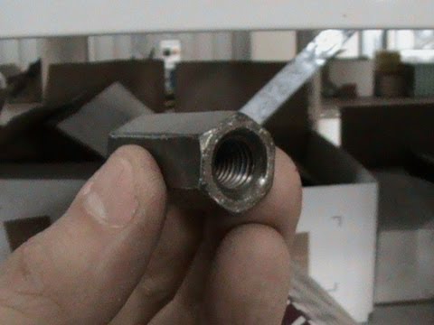
Before approving production, inspect length, across-flats dimension, end chamfers, thread size and pitch, thread gauges from both ends, coating thickness, surface condition, hardness or proof load where applicable, and traceability. Assemble samples with the specified rods. Confirm insertion depth, wrench access, running behavior, locking method, alignment, and required axial load.
Use the thread engagement guide to organize calculations, then document the approved stack. A useful RFQ includes a drawing, standard, materials, grades, finish, lubricant, minimum engagement per side, sight-hole requirement, load case, environment, retention method, certificates, packaging, and quantity.
Only a reducing or custom coupling nut designed with the two specified internal threads can do that. A standard coupling nut normally expects the same diameter, pitch, thread system, tolerance, and hand at both ends.
Equal engagement is a useful assembly target for a symmetric joint, but the required minimum must be established by the governing standard or engineering calculation. A visual halfway rule alone does not prove thread strength.
No. Capacity also depends on nut and rod materials, property classes, thread quality, effective engagement, tolerances, coating, and the complete load case. Additional length is useful only when the threads and body are designed to use it.
A plain coupling nut is not automatically self-locking. If vibration or rotation is possible, specify and validate a compatible retention method such as jam nuts, adhesive, or a purpose-designed mechanical lock.

 TNHO
TNHO 


