Fastener coating thickness must be specified together with the layer system, measurement location, inspection method and final thread acceptance. A single reading on a screw head cannot prove that every thread surface has an acceptable deposit, and a coating certificate cannot replace a functional fit check. OEM buyers should agree both the required protection and the space available for the coating before production. This guide explains how to turn a vague thickness request into a repeatable inspection plan, while avoiding universal micrometre limits and unsupported thread calculations. All numerical acceptance values must come from the approved drawing and applicable coating specification.
List the substrate, deposited layer, conversion treatment, sealant, topcoat and lubricant where applicable. State whether the requested value refers to one layer or the completed system. Two suppliers can honestly report different values if one measures the metallic deposit and another reports a total layered thickness. Resolve that ambiguity before requesting samples.
Use the TNHO hex socket screw product range as a geometry reference, not a certified thickness sample. The unpatched cylindrical-head screws in this article show surfaces that need consideration during inspection. A blue locking patch is a separate feature and must not be mistaken for the metallic protective deposit. The plating and galvanizing comparison provides broader process context; the present guide addresses how a selected system is measured and accepted.
Identify the coating standard, its revision and any drawing-specific additions. Review the scope for the substrate, thread system and coating process. A standard intended for one system should not be applied to a different process merely because both produce a silver surface. Keep mechanical, dimensional and corrosion requirements distinct in the purchase specification.
ISO’s official ISO 4042:2022 listing describes electroplated coating systems for fasteners and identifies a published amendment. The public scope helps confirm relevance; it does not supply every contractual acceptance detail. Obtain the controlled applicable text and state whether amendments are included. Do not use an old online chart as a substitute for the selected edition when approving a production lot.

Create a simple location map using the engineering drawing or a marked reference photograph. Distinguish head surface, shank, thread area, recess and any critical bearing or contact face. For small curved parts, confirm that the selected instrument can isolate the intended area. A position name such as near the thread is not precise enough for two laboratories to repeat the measurement.
Agree the number of parts, readings per part and treatment of rejected or inaccessible locations. Identify whether reported values are individual local readings, averages or another defined statistic. Preserve the actual observations rather than only a final pass stamp. A supplier should not choose the easiest accessible surface after testing if the purchase requirement concerns a different functional area. If the geometry prevents the chosen method, resolve the inspection approach before coating the production order.
A thickness instrument is not universal. Match its measurement principle to the layer composition, substrate and part geometry. Require the laboratory to document the method, calibration basis, specimen positioning and limitations. If a multilayer system is present, verify which layers the instrument can distinguish and how its reported result should be interpreted.
ASTM B568 covers X-ray spectrometry for metallic and some nonmetallic coatings; conversion to linear thickness depends on coating density. The NIST surface-engineering measurement guide provides useful method background. Neither source means that one instrument setup is automatically valid for every screw. Discuss the actual material combination and geometry with the qualified laboratory and document the agreed procedure.
| Decision | Information to request | Acceptance action |
|---|---|---|
| Layer definition | Substrate, metallic layer, topcoat and lubricant | Identify which thickness is accepted |
| Location | Drawing map of required measurement areas | Report local observations at those locations |
| Method | Principle, calibration and geometry limitations | Approve applicability before production |
| Thread function | Before-finish and after-finish requirements | Perform the specified finished-thread check |
| Decision rule | Units, limits and uncertainty treatment | Resolve boundary results consistently |
This is a purchasing decision checklist, not a table of universal material or coating limits. Use the approved drawing and applicable standard for numerical acceptance.
A protective deposit occupies space on surfaces that must still engage. Review the thread requirement before finishing and the acceptance requirement after finishing. The design owner and supplier should agree how the original thread dimensions accommodate the selected system. Do not rely on forcing a finished part into a mating nut to make it acceptable.
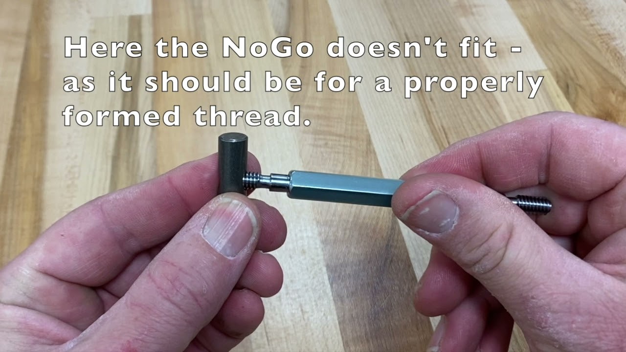
Use the specified functional inspection for the completed thread and investigate resistance beyond the approved method. A head-surface reading and a gauge result answer different questions: one describes a measured coating location; the other evaluates the specified thread function. Retain both when both are required. The thread gauge inspection guide helps buyers prepare the inspection record. Do not introduce an improvised gauge torque, engagement length or coating allowance without the applicable engineering basis.
Coating acceptance should consider features beyond the external thread. A drive recess must accept the intended tool, a locating hole must retain its function, and a bearing face must meet the drawing requirements. Surface buildup or retained material can interfere with assembly even when a chosen thickness reading appears acceptable.
Show masking requirements and protected interfaces explicitly. If an electrical contact must remain bare, identify its boundary and the permissible transition. If the entire part must be coated, state how recessed areas are addressed and inspected. Avoid describing the coating as uniform unless the measurement evidence supports that statement. A useful first article review combines the agreed thickness observations with dimensional and assembly checks on the same representative process. Keep findings connected to specific features so corrective action addresses the actual interference.

Ask the laboratory to provide units, resolution and the applicable measurement uncertainty or decision rule. A reported result at a limit needs an agreed interpretation; purchasing staff should not round it toward acceptance without authorization. Also check whether a reading represents the location required by the specification rather than a nearby convenient surface.
When two laboratories disagree, compare substrate identification, layer model, calibration, positioning and sample preparation before deciding that one instrument is defective. Retain representative parts for a controlled comparison. A destructive check, if selected, should be performed under an approved method with identified sampling and locations. Do not compare unrelated measurements as if they were direct repeats. Record the final decision and its evidence so the same dispute does not reappear on the next shipment.
Thickness is one characteristic of a coating system. The protection achieved also depends on the specified process, surface condition, coverage, environment and damage during use. A passing thickness report does not establish a universal number of outdoor years. Likewise, a laboratory corrosion result must retain its stated test method and acceptance conditions.
If corrosion testing is required, identify representative finished parts, conditioning, observations and failure criteria separately from thickness inspection. The fastener salt-spray guide explains how to interpret that evidence without treating test hours as a direct lifetime conversion. Keep installation requirements in the review as well. A surface system that changes assembly behavior needs qualification of the actual connection, not simply a thicker deposit requested to improve a purchasing scorecard.
A complete report identifies the supplier, finishing source, drawing revision, purchase order, lot, substrate, coating system and governing method. Include the measurement-location map, sample selection, actual values, units and decision rule. Connect final thread inspection to the same finished lot where required. Store raw observations alongside the final disposition.
For recurring production, define changes that require notification: a new coating source, altered layer system, different lubricant or a changed measurement method. Approve the effect on thickness interpretation and assembly before release. When a lot fails, separate containment from process correction and retain evidence of the reinspection. Reworking a finish can change more than its appearance, so define what must be revalidated. A controlled report turns a thickness number into usable production evidence without implying untested performance.
This neutral manufacturing-training video illustrates functional thread inspection. It complements the discussion of finished-thread acceptance; it does not measure coating thickness or establish a gauge requirement for your drawing.
No. It measures the identified location under the selected method. Agree thread-area evidence and final functional inspection separately.
Do not assume it can. Select a method suitable for the coating, substrate, geometry and required uncertainty.
No. Environmental performance requires separate evidence for the complete system and intended exposure.
Include lot identity, substrate and coating system, method, locations, sampling, actual values, units, decision rule and the applicable acceptance specification.

 TNHO
TNHO 


