A clear thread runout specification tells the manufacturer where full-form external threads must end and how the incomplete transition toward an unthreaded shank will be controlled. Runout is not usable thread engagement. If a nut, insert or tapped component reaches that transition, it may jam before seating and the joint may not achieve its intended preload. On a drawing, define the usable full-thread length from a known datum, identify any allowed incomplete-thread zone or relief, and verify the assembled grip stack. Do not assume that a nominal screw length or a phrase such as “fully threaded” resolves the transition in a custom part.
On a partly threaded screw, the forming or cutting tool cannot change from full thread depth to a smooth shank at a mathematical line. There is a transition where the thread profile becomes incomplete. That is the runout. A similar but distinct region can occur at the lead end of a screw or at the bottom of a blind tapped hole. A deliberately machined undercut or thread relief can make space for the tool and allow a mating component to seat closer to a shoulder, but it is a separate design feature that must be dimensioned.
Buyers should ask which length is being reported. “Thread length” in a catalog may not tell you the location of the last complete thread under a shoulder. “Shank length” does not describe an under-head fillet or the condition at the first incomplete turn. For a custom stepped bolt, the location of the usable thread relative to the shoulder is often more important than the total number of visible turns.

A nut or female thread expects a compatible full profile along its engagement. If it enters incomplete runout at the base of a screw, interference can stop it before the joint stack is clamped. A torque wrench may still indicate resistance, but that resistance is not necessarily the intended preload. A designer can avoid the conflict by selecting a suitable grip length, using an approved washer stack, shortening the mating thread’s travel or specifying a relief, subject to joint design requirements.
NASA-STD-5020 gives a useful, explicitly aerospace-context example: its bolt-grip guidance warns that nut or insert threads must not encroach on incomplete runout, and that blind tapped holes must avoid bottoming or incomplete internal threads. The standard describes an incomplete runout zone of up to twice the pitch on many commercial aerospace fasteners. That figure is not a universal allowance for every fastener. Use the actual applicable product standard and drawing to set the limit for this project.
Choose a datum that a supplier and inspector can find reliably, commonly an under-head bearing face or a defined shoulder face. Dimension from it to the last full-form thread and to any relief boundary. State the external thread designation and tolerance class. For a part with multiple diameters, identify exactly which step carries the thread and which surface locates the joint. If a shoulder must bear in a hole, do not rely on a nominal overall length to establish the useful engagement at the far end.
The drawing should distinguish minimum full-form thread length from maximum runout extent. A minimum ensures the mating thread can obtain the intended usable engagement; a maximum prevents the incomplete zone from entering the nut or interface. If the design needs full threads nearly to a shoulder, review tool access and whether an undercut, modified forming method or alternate assembly is practical. Do not add a sharp relief without assessing fatigue and load path.
| Feature | Where it occurs | What the drawing should control | Assembly concern |
|---|---|---|---|
| External thread runout | Between full threads and unthreaded shank/shoulder | Last complete thread and allowed transition extent | Nut may interfere before clamping |
| Thread relief or undercut | Purpose-made recess at the transition | Location, width, diameter, radius and surface requirements | May improve seating but affect fatigue or bearing |
| External lead threads | Entry end of a screw | End form and usable full-thread length | First turns are not full engagement |
| Blind-hole incomplete threads | Bottom of a tapped hole | Minimum full thread depth and bottom clearance | Screw can bottom before joint is tight |
The table is a functional comparison, not a dimensional standard. ISO 3353-1 covers lead and runout requirements for rolled external threads in aerospace construction and an inspection method for disputes. Its scope is specific; citing it for an ordinary custom meter screw without project adoption would be misleading. For unified inch threads, ASME B1.1 governs thread form, series, classes and designations, while the finished-part drawing still needs to define the functional transition as required.
Take the under-head bearing face as the starting point and add the real clamped layers: panel thickness, any approved washers, spacer and nut or insert position. Consider the tolerance of each layer, not only the nominal sum. Locate where the female thread first engages the external screw and where it stops after the joint seats. Compare that travel with the minimum full-thread region and the maximum incomplete runout. In a blind hole, also compare screw penetration with usable tapped depth and bottom clearance.
A drawing review should answer both worst cases: the thinnest stack might move the nut toward runout, while the thickest stack might reduce the number of engaged full threads. Changing a washer or gasket can make a previously safe bolt grip unsuitable. The mating components, installation process and preload target matter. For a deeper treatment of engaged threads, see our thread engagement length guide; for overall dimensions, see screw length tolerance.

Rolled and cut threads do not necessarily leave identical transition shapes. Tooling, blank diameter, shoulder geometry and production setup constrain where complete threads can begin or end. An extremely short runout requirement may require special tooling, a relief or a different part geometry. Discuss manufacturability before freezing a tolerance. A vendor quotation should identify exceptions to the drawing, not quietly interpret “full thread” as “as close as practical.”
For a custom stepped fastener, inspect the reference part’s head, shank, shoulder and threaded tip as separate controlled features. TNHO’s custom bolt product family shows examples with different shank and thread arrangements. The photographs establish product relevance; they do not certify a particular runout length or application load. Supply a controlled drawing and a mating-part sample when asking for a custom transition.
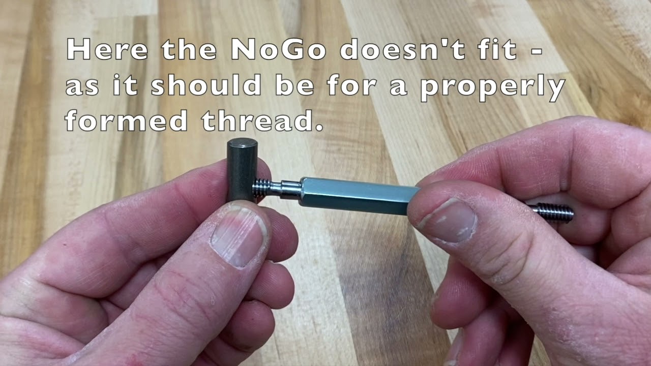
A GO/NO-GO thread gauge can assess the designated thread’s fit, but a simple pass on one portion does not establish where the final full-form thread ends relative to the shoulder. Use a profile projector, optical system, microscope or suitable comparator and a documented datum when the transition dimension is critical. Inspect representative samples at the agreed stage, especially if a coating or secondary operation could change geometry. Report the last complete thread location, runout or relief dimensions and gauge results separately.
For a disagreement, preserve the part and record the drawing revision, calibration status, measurement method, magnification and operator. Agree on what counts as a complete thread flank. Do not rework the sample before documenting the as-delivered condition. In our GO/NO-GO gauge inspection guide, the limit gauge checks thread acceptability; this article addresses the location and shape of the transition. These are complementary, not identical, inspection decisions.
Dimensioning only overall length: The supplier cannot derive a unique last-full-thread position. Calling every visible turn “usable”: The lead and runout may be incomplete. Using a universal two-pitch rule: A rule from a particular standard or fastener family may not apply. Ignoring the nut’s travel: A correct screw in isolation may still jam in the assembled stack. Adding a relief without analysis: A deep, sharp undercut may harm fatigue performance. Inspecting only with a ring gauge: Fit does not locate the runout boundary against the shoulder datum.
To resolve ambiguity, issue a drawing that separately defines the thread, full-form region, transition, relief if any, and joint clearance. Ask the supplier to return an annotated manufacturing proposal when a feature cannot be achieved with the intended process. Approve a change only after the mating part, strength and inspection requirements are reviewed together.

This Manufacturing Production Technology Academy demonstration shows a GO/NO-GO thread check. It helps visualize the functional-fit inspection performed after a thread is made; it does not measure the runout dimension, which must be checked separately from a defined datum.
No. Incomplete transition threads should not be assumed to provide the same engagement as the specified full-form region.
No. It is one design solution when a mating component must approach a shoulder closely, but it must be assessed for strength and manufacturing effects.
It can check functional thread fit under its procedure, but it does not directly dimension the last complete thread from an under-head or shoulder datum.
Send the controlled screw and mating-part drawings, full-thread length requirement, transition/relief limits, tolerance stack and agreed inspection method.

 TNHO
TNHO