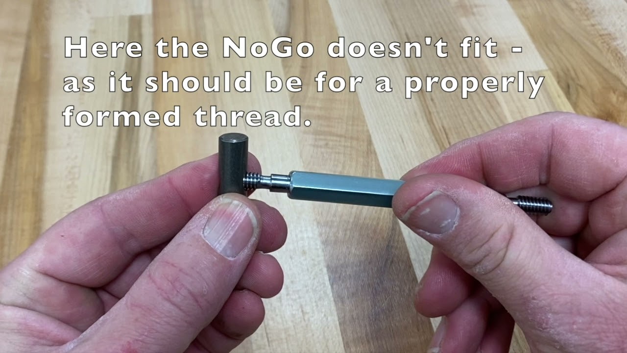
Go/no-go thread gauge inspection is a fast way to decide whether a specified screw thread falls within its acceptance limits. For an external screw, an appropriate GO ring should pass along the required usable thread length without force, while the NO-GO ring must not exceed the engagement allowed by the applicable standard and inspection plan. Internal threads use corresponding plug gauges. The actual limit is not a universal “never enters” rule: it depends on the thread system, gauge type and governing standard. A buyer should specify the thread designation and class, the gauge system, inspection length and treatment of coatings before accepting a supplier’s “gauge passed” report.
A limit gauge provides a practical pass/fail check against specified thread boundaries. It does not report the measured pitch diameter, the exact flank angle or the clamp load that a finished joint will develop. For a screw, the GO ring tests whether a functional mating profile can travel over the required thread. The NO-GO ring checks the opposite size limit under the rules of the particular gauge system. A plug performs the corresponding checks for an internal thread. The standards distinguish a functional acceptance check from a full dimensional characterization; ISO 1502 describes gauges for ISO metric workpiece threads, while ASME B1.3 establishes acceptance systems for several inch and metric thread forms.
That distinction matters in purchasing. A caliper reading across the screw crests may show a plausible major diameter even when pitch, flank form or accumulated lead error prevents assembly. Conversely, a gauge can pass while the fastener fails a separate requirement for length, head geometry, material, surface condition or coating. Treat the gauge result as one inspection record tied to a complete drawing, not as a substitute for the drawing.

Start with the designation on the engineering drawing. “M6” alone may omit pitch and tolerance class; “1/4 inch screw” omits series, threads per inch and class. Identify whether the feature is external or internal, metric or unified, right- or left-hand, and whether the intended thread has a special form. A ring gauge intended for an external product thread cannot be exchanged for a plug intended for an internal one. A plain hole gauge does not verify thread flanks.
Verify the gauge marking, calibration status, wear condition and compatibility with the prescribed acceptance system. Adjustable rings may require setting against a master in accordance with their procedure. A coating or nylon patch can affect engagement and may require a drawing-specific inspection sequence; never force a gauge over a locking feature and then count the damage as a valid test. For TNHO hex socket screws, for example, the product family includes different lengths and anti-loosening options. The product page is a geometry reference, not a claim that every variant shares one gauge or material.
GO failure can arise from oversize effective thread geometry, pitch or form error, burrs, contamination or gauge mismatch. Excessive NO-GO engagement can indicate an undersize effective thread, wear or an incorrect gauge. Neither result by itself identifies the root cause. Segregate the lot, preserve failed samples and measure the relevant characteristics before deciding on rework or concession.

For a tapped hole or threaded insert, use the designated GO and NO-GO plug gauges. Confirm the specified minimum usable depth rather than merely checking the entrance. A blind hole can accept the first turns while remaining too shallow for the screw, and a bottoming tool may leave incomplete threads near the base. The plug should be introduced squarely by hand without using it as a cutting tool. Debris, plating buildup and damaged entry chamfers can create a false rejection or mask a production issue if the operator forces the gauge.
If the joint includes an insert, sheet-metal nut or captive component, inspect the assembly in its final state when the drawing requires it. Installation can distort a thread that passed as an individual component. Record whether the gauge check happened before or after plating, heat treatment, insertion or final assembly. This is especially relevant for self-clinching nuts and standoffs used with panel fasteners.
| Observation | Immediate interpretation | Next check before disposition |
|---|---|---|
| GO gauge will not reach specified usable length | Functional fit is not demonstrated | Confirm correct gauge and class; inspect burrs, pitch, lead and coating |
| GO passes; NO-GO engagement remains within the governing limit | Thread passes this defined limit-gauge check | Complete other drawing and lot-inspection requirements |
| NO-GO exceeds permitted engagement | Opposite thread size limit may be violated | Verify gauge setting/wear and measure the workpiece pitch diameter |
| Result changes after coating or insertion | Process may alter the final thread | Compare before/after stages; apply the drawing’s final-state requirement |
This is a decision guide, not a universal numerical acceptance table. The permissible NO-GO engagement and the length over which GO must pass come from the stated gauge system and part specification. Applying an inch-thread rule to a metric gauge, or treating a company practice as a standard, can reject good parts or accept bad ones.
A limit gauge is efficient for production screening and receiving inspection, but it is intentionally not a dimension-reading instrument. When a lot fails or the fit margin matters, use calibrated dimensional methods appropriate to the thread: pitch-diameter measurement, optical examination of the profile, lead/pitch verification and inspection of crest/root condition. The NIST-hosted historical screw-thread commission report explains why GO and NO-GO gauges address different boundaries, though the current project standard must control acceptance rather than an older general reference.
For a screw with a nylon patch or other prevailing-torque feature, separate thread geometry from locking performance. Do not remove the patch to obtain a pass unless the drawing explicitly authorizes that method. Verify the locking feature through its own applicable test plan. A gauge that passes says nothing about resistance to loosening in the installed joint. Related decisions about drive access and assembly are covered in our Torx versus hex socket guide, while fit between mating parts also depends on the clearance hole and thread engagement length.
Specify the complete thread callout, referenced standard edition, usable thread length, any special lead or runout requirements, coating condition at inspection and the acceptance method. State whether inspection is on every part, a defined sample or a process-controlled lot. Request a record linking gauge ID and calibration status to the measured lot, drawing revision, operator/date and any nonconforming disposition. Where an alternate gauge system is proposed, engineering should approve the equivalence rather than leaving it to a verbal understanding.
For custom hardware, send both the fastener drawing and the mating-part interface. A supplier can then evaluate whether the selected gauge reaches the meaningful section of the thread and whether an under-head feature, shoulder or coating alters the method. Where the product is safety-critical or regulated, the approved project specification overrides this general guide. Do not infer an acceptance value from a blog image or a nominal thread size alone.
Forcing the gauge: A ring or plug is not a rethreading tool. Force can damage both the gauge and the product, erasing the original evidence. Checking only the lead: The entry may fit while the useful thread length does not. Mixing classifications: Similar nominal diameters do not make different pitches or classes interchangeable. Ignoring the final condition: Plating, patch application and insertion can change the fit. Calling a part good after one pass: Material, length, head and surface requirements still need their separate checks.
The most useful corrective action is to connect each failure to a specific measured characteristic. A repeated GO failure after coating calls for investigation of buildup and process sequence; a failure limited to the first turn calls for a lead or burr check; a lot-wide NO-GO issue may require confirming the manufacturing setup and gauge setting. This avoids “adjusting until it feels right,” which cannot be audited.

The Manufacturing Production Technology Academy demonstration below shows the hand-check sequence for a GO/NO-GO thread gauge. Use it to visualize the inspection step, then apply the specific standard and drawing limits for your part.
It needs to cover the specified usable threaded length under the applicable method, not necessarily the unthreaded shank or every portion of an overall part. The drawing must define that length.
Do not use a universal answer. Permitted engagement differs with thread system, gauge type and the invoked standard. Record actual engagement and compare it with the approved acceptance rule.
No. Preload also depends on joint geometry, material behavior, friction, installation method and other controlled features. Gauge acceptance is only one part of the joint verification.
No. A caliper can help check an outside diameter but does not test the complete functional thread profile or cumulative fit.

 TNHO
TNHO