Metallographic specimen preparation for small fasteners starts with selecting the right section and preserving the feature that must be examined. Cutting, mounting, grinding, polishing and any later etching must reveal the material rather than create an apparent defect or remove the evidence. A mirror-bright surface is not enough if its orientation is wrong, its edges are rounded or its preparation history is unknown. This guide explains how buyers and quality teams can request a useful prepared section, recognize common limitations and keep the resulting images connected to the actual part and inspection question.
Different questions require different locations and preparation choices. A thread-root investigation, a head-to-shank transition review and a coating cross-section do not necessarily use the same section. Before a laboratory cuts a sample, identify the feature on a drawing and explain what decision the examination must support.
For a real hex socket screw, a longitudinal plane can show relationships along the axis, while a transverse plane can reveal a different view through a selected region. Neither is universally better. The selected plane must intersect the feature of interest and retain a reliable orientation record.
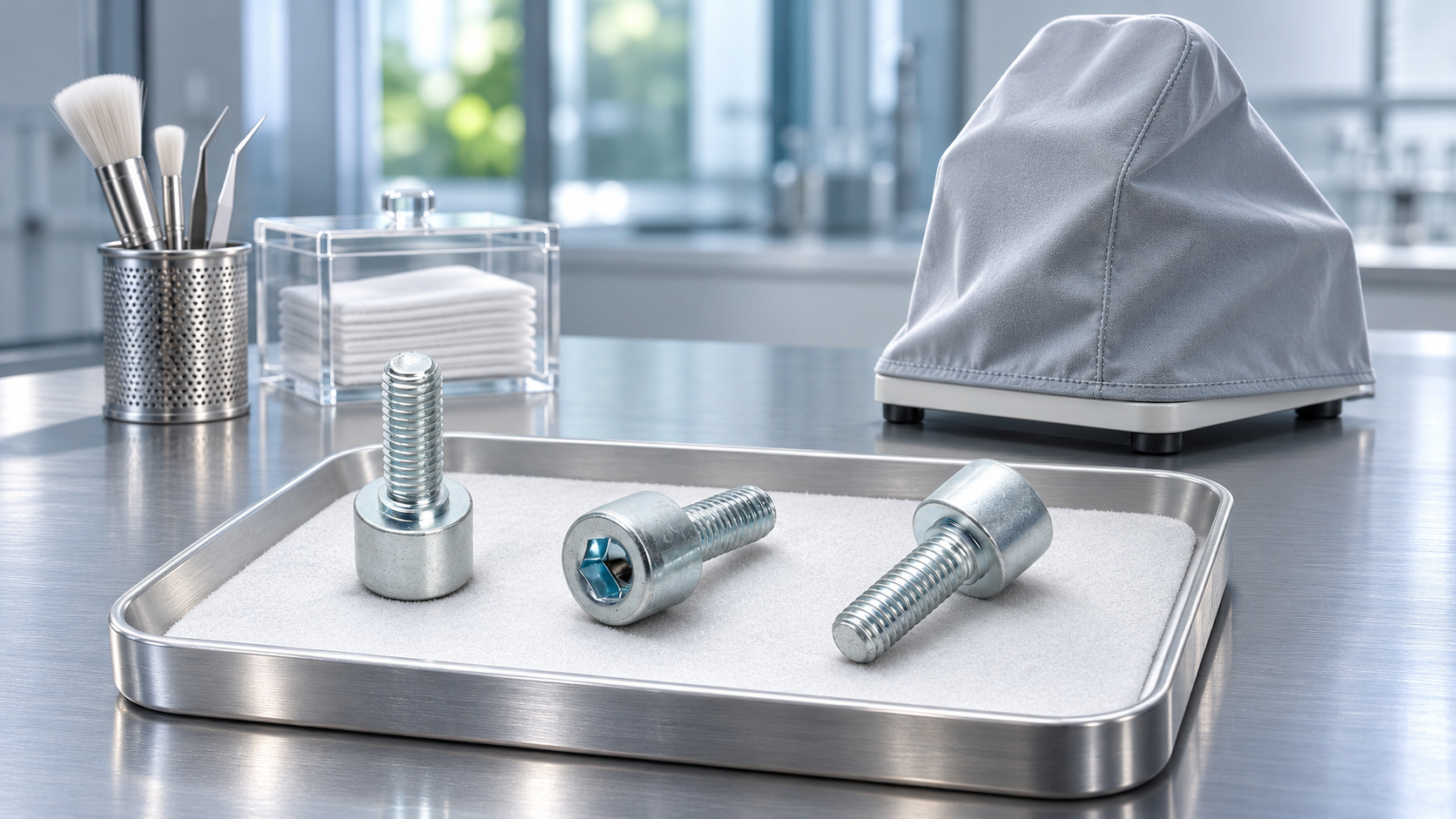
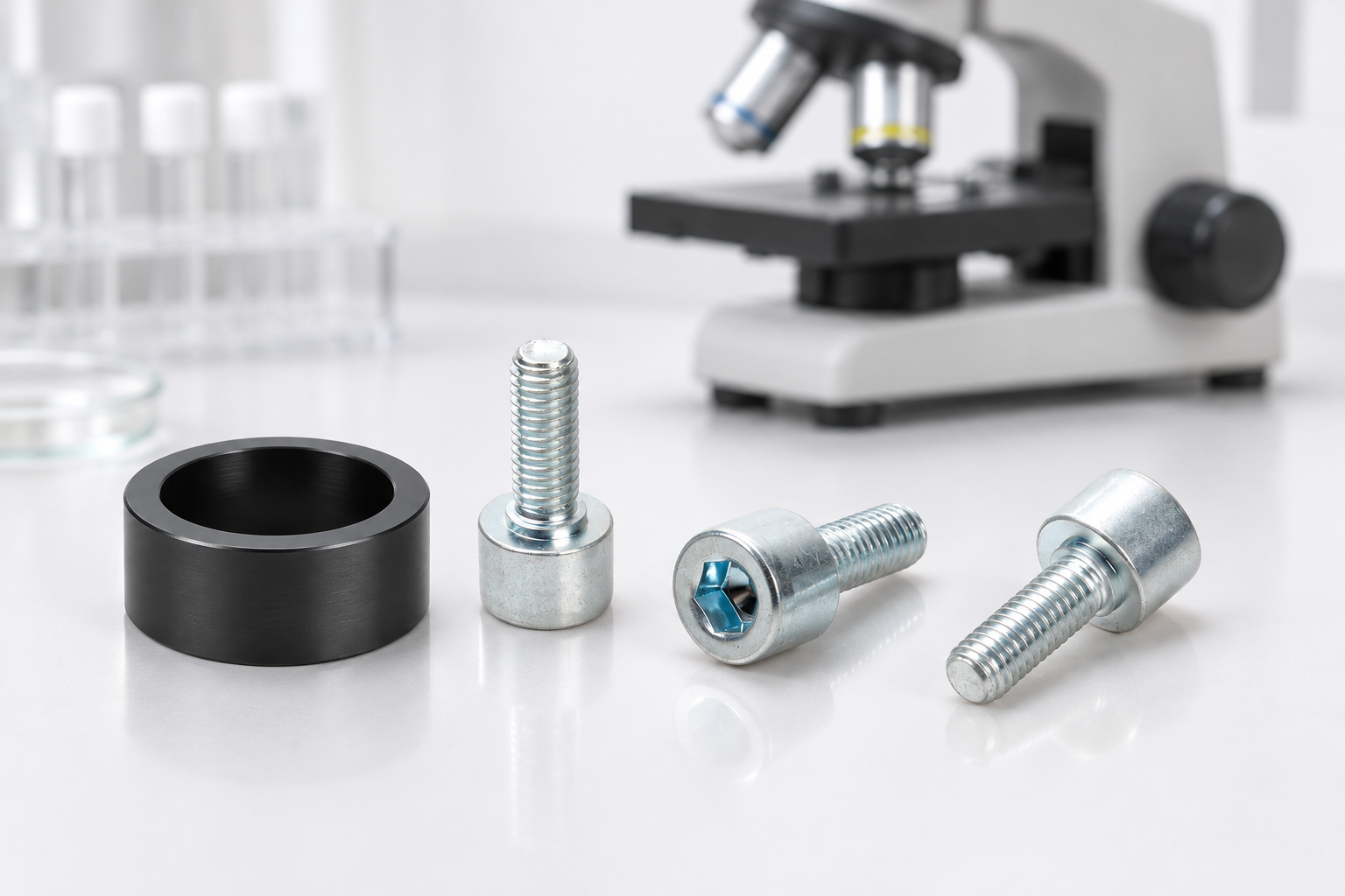
The product photograph in this guide is an exterior reference, not evidence of the pictured screw’s internal structure, steel grade or coating. Confirm those facts through the applicable order records. If the feature is associated with a reported failure, preserve the damaged component and obtain an investigation plan before any destructive preparation takes place.
ASTM E3 provides guidance for preparing metallographic specimens. Its public description emphasizes specimen selection and preparation as central to revealing material structure. It does not establish a single preparation recipe that is valid for every alloy, coating and fastener feature.
ASTM E407 concerns microetching metals and alloys. It addresses a later operation with its own material selection and safety considerations. Do not assume that every polished specimen needs etching or that one etchant is suitable for all components. The examination objective and applicable method should determine whether etching is necessary.
Preparation is also separate from the acceptance rule. A section can be prepared competently while the inspection requirement remains unspecified. Connect the finished specimen to the relevant microstructural, dimensional or defect assessment method, and identify who is responsible for interpreting compliance with the drawing or material specification.
Record part number, lot or heat identity, sample condition and the position selected for sectioning. Photograph the intact part with a meaningful orientation reference. If several fasteners will enter one mount, prepare a map that identifies each one independently and can survive later grinding and handling.
Marking must not damage the surface being investigated. Use an approved identification approach and keep labels away from critical evidence. A mark placed near a suspected crack, corrosion site or coating defect can complicate interpretation. When the specimen is very small, its container and mount map may be more reliable than attempting to mark the component directly.
Keep a retained comparison sample when the investigation allows it. Destructive preparation cannot always be reversed, and further examination may require an untouched surface. Agree whether the laboratory may consume the entire part or must preserve a remainder. Record the location of retained pieces so they can be matched to the prepared section later.
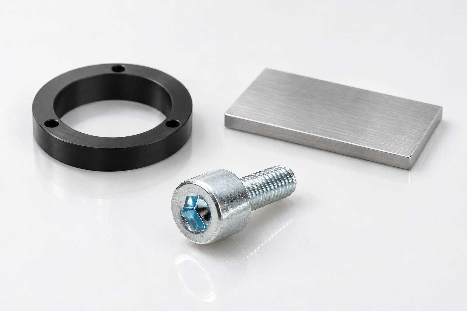
Cutting can add heat, deformation or damage near the new surface. The laboratory should choose a sectioning approach that controls those effects for the material and feature being examined. Cutting directly through the only visible evidence without a plan can remove the very region the investigation needs.
Where suitable, allow preparation material so later grinding reaches the intended plane without retaining cutting damage. The allowance and cutting method are specimen-specific choices, not universal values supplied by this article. Ask the laboratory to explain how it will confirm arrival at the required plane and avoid grinding past a shallow feature.
Geometry makes small fasteners challenging. A nominally central longitudinal cut can miss the true axis, changing apparent thread and head relationships. If the analysis depends on an axial section, the laboratory should document how orientation was controlled and how the final section was verified. A polished oblique plane should not be interpreted as a true central profile.
Mounting helps handle small components and support features during preparation. Resin selection and mounting conditions must suit the specimen. Heat, pressure, shrinkage and gaps at the specimen boundary may matter, especially for delicate surfaces, coatings or materials whose original condition must be preserved.
A gap beside the component can trap abrasive or cleaning residue. Poor support can also lead to edge rounding during polishing. If the critical observation lies at a thread crest, coating edge or near-surface layer, ask specifically how the chosen mounting method will protect that boundary.
Mounting orientation should match the section plan. A securely mounted part can still be useless if it presents the wrong plane. Retain a readable identity on the mount and a record connecting it to the original photograph. Multiple samples in one mount require both enough support for preparation and enough separation to avoid identification mistakes.
| Preparation stage | Evidence to preserve | Problem to check before proceeding |
|---|---|---|
| Sample selection | Identity, condition and reason for examination | Unrepresentative part or lost lot connection |
| Sectioning | Intended plane and cutting history | Heating, deformation or missing the feature |
| Mounting | Orientation and specimen map | Unsupported edge, resin gap or ambiguous identity |
| Grinding | Progress toward the target plane | Remaining cutting damage or overgrinding |
| Polishing | Clean surface with retained geometry | Pullout, relief, scratches or rounded edges |
| Examination and etching | Images and preparation sequence | Confusing preparation contrast with real structure |
This table organizes practical concerns from the linked ASTM preparation and etching guidance. It contains no fixed machine settings or acceptance limits. Those belong in the laboratory’s validated procedure and the applicable inspection specification.
Grinding should bring the specimen to the intended plane while removing earlier damage. Each stage must be assessed before advancing. A later fine polish may produce a glossy surface while leaving deeper scratches or deformation from an earlier operation. Surface appearance under casual lighting does not establish microscopic readiness.
Keep abrasive stages and cleaning arrangements controlled. Carrying coarse particles into a finer stage can introduce new scratches. Clean the specimen and relevant holders between stages using a method compatible with the material and mount. The laboratory should avoid introducing residues that would confuse a subsequent examination.
Polishing must retain the relationships being measured. Materials and phases with different responses can develop relief, while weakly supported particles can pull out. An apparent cavity or boundary may therefore be a preparation artifact. Ask the laboratory to assess suspicious features and document any repolishing before interpreting them as manufacturing defects.
Avoid prescribing a universal load, speed, abrasive sequence or polishing time from an online article. The appropriate choices depend on material, geometry and purpose. A useful purchasing instruction defines the required feature preservation and report evidence, leaving method settings to a qualified laboratory with a controlled procedure.
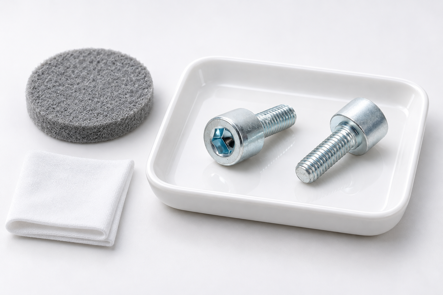
An initial unetched examination can preserve information about scratches, cavities, coatings and other features before etching changes contrast. Save relevant images and locations. If an inclusion assessment is intended, follow that method’s required preparation and examination sequence rather than relying on a later etched micrograph.
Etching is a controlled analytical step, not simply a way to make every image look more detailed. It can reveal microstructural features, but overetching or an unsuitable procedure can obscure boundaries and complicate interpretation. Chemical selection and handling require the laboratory’s approved safety controls. This guide intentionally supplies no chemical mixing recipe.
For an investigation involving surface carbon changes, coordinate preparation with the separate fastener decarburization guide. Surface preservation, orientation and the required evaluation method must be established before interpreting a near-surface band. A rounded or damaged edge can make a persuasive-looking image misleading.
Long straight scratches can cross several features without following the material structure. Pullout can leave dark pits, and polishing relief can create focus differences or apparent boundaries. Embedded particles may resemble constituents that belong to the steel. These observations call for a preparation review before a defect conclusion.
A laboratory may need to examine adjacent fields, adjust illumination or repolish a controlled amount to clarify a suspicious feature. Such follow-up should retain a record of the original state and the change made. Do not replace the first image silently, because the investigation may depend on whether a feature persisted or changed during preparation.
Coatings and very thin surface regions deserve special care. Edge rounding can alter apparent thickness or continuity, and an oblique section can distort dimensions. If quantitative measurements are requested, confirm that the section geometry, calibration and method are appropriate. Preparation quality and measurement validity need to be considered together.
The thread rolling laps guide addresses a distinct manufacturing concern. A prepared section may support that investigation, but a single dark line should not be labelled a lap without considering orientation, preparation artifacts and the applicable examination evidence.
A useful report includes the specimen identity, section orientation, preparation condition and relevant examination method. Images should contain valid scale information and enough context to locate the feature. A highly magnified crop without a low-magnification locator can be difficult to connect to the actual screw.
Record whether each image is unetched or etched and identify any additional preparation between images. If the same location is compared before and after etching, make that relationship explicit. Keep original image files and the mount map when the work supports a quality decision or a later investigation.
Use the broader fastener PPAP guide to connect the report with drawing revisions, sample records and approval decisions. Preparation evidence is valuable because it explains how the image was obtained; the final acceptance statement still needs the applicable requirement and an authorized interpretation.
The university teaching video below introduces metallographic sample preparation. It helps explain the sequence from a physical specimen to an examinable surface. The example is educational and does not show internal observations or test results from the TNHO product illustrated in this article.
No. The specimen may still have the wrong orientation, subsurface deformation, relief or rounded edges. Check preparation quality against the intended examination, not brightness alone.
No. Etching depends on the examination objective and applicable method. Preserve relevant unetched observations before deciding whether a suitable etching step is needed.
Not necessarily. Inclusion assessment, coating examination and microstructural evaluation can require different planes or preparation conditions. Agree compatible examinations before cutting the component.
Provide the drawing, material and lot records, investigation question, desired section location and any destructive sampling limits. Request a specimen map, preparation history and images with reliable location and scale information.

 TNHO